

Question: Analyze the earth retaining system shown in the figure using the software FREW ( The example FREWman in the FREW manual could be used as
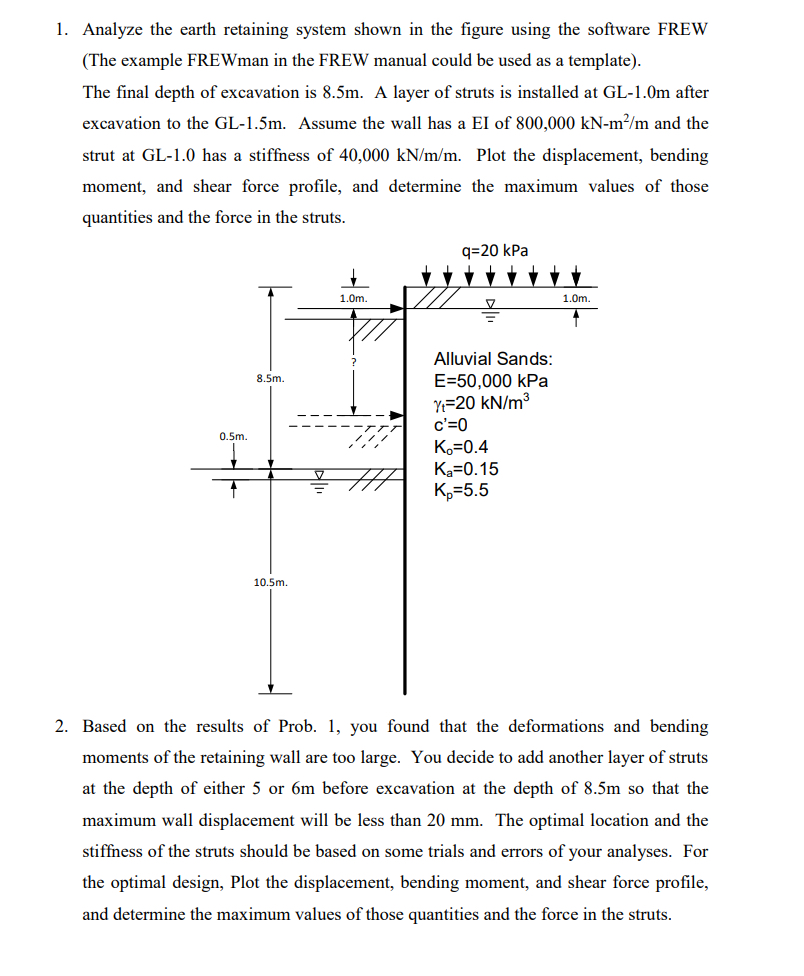
Analyze the earth retaining system shown in the figure using the software FREW The example FREWman in the FREW manual could be used as a template
The final depth of excavation is A layer of struts is installed at GLm after excavation to the GLm Assume the wall has a EI of and the strut at GL has a stiffness of Plot the displacement, bending moment, and shear force profile, and determine the maximum values of those quantities and the force in the struts.
Based on the results of Prob. you found that the deformations and bending moments of the retaining wall are too large. You decide to add another layer of struts at the depth of either or before excavation at the depth of so that the maximum wall displacement will be less than The optimal location and the stiffness of the struts should be based on some trials and errors of your analyses. For the optimal design, Plot the displacement, bending moment, and shear force profile, and determine the maximum values of those quantities and the force in the struts.
FREW is Flexible REtaining Walls
Step by Step Solution
There are 3 Steps involved in it
1 Expert Approved Answer
Step: 1 Unlock

Question Has Been Solved by an Expert!
Get step-by-step solutions from verified subject matter experts
Step: 2 Unlock
Step: 3 Unlock