Question: ANSWER QUESTIONS 21. What is UML? 22. What is the purpose of UML use case diagrams? 23. What is another name for actor in UML,
ANSWER QUESTIONS
21. What is UML?
22. What is the purpose of UML use case diagrams?
23. What is another name for "actor" in UML, and
how is it represented on a use case diagram?
24. What is the automation boundary on a use case
diagram, and how is it represented?
25. How many actors can be related to a use case on
a use case diagram?
26. Why might a systems analyst draw many different
use case diagrams when reviewing use cases with end-users?
27. What is the "includes" relationship between two use cases?
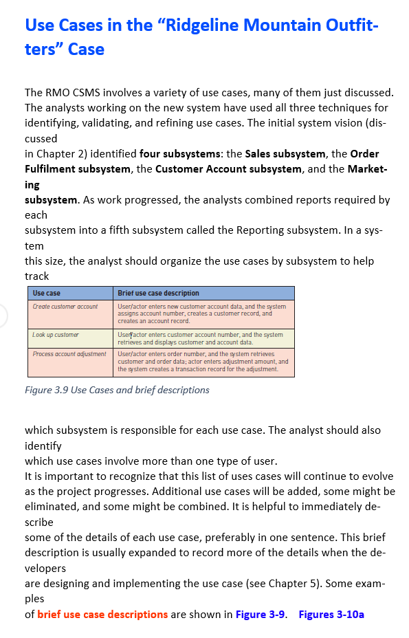
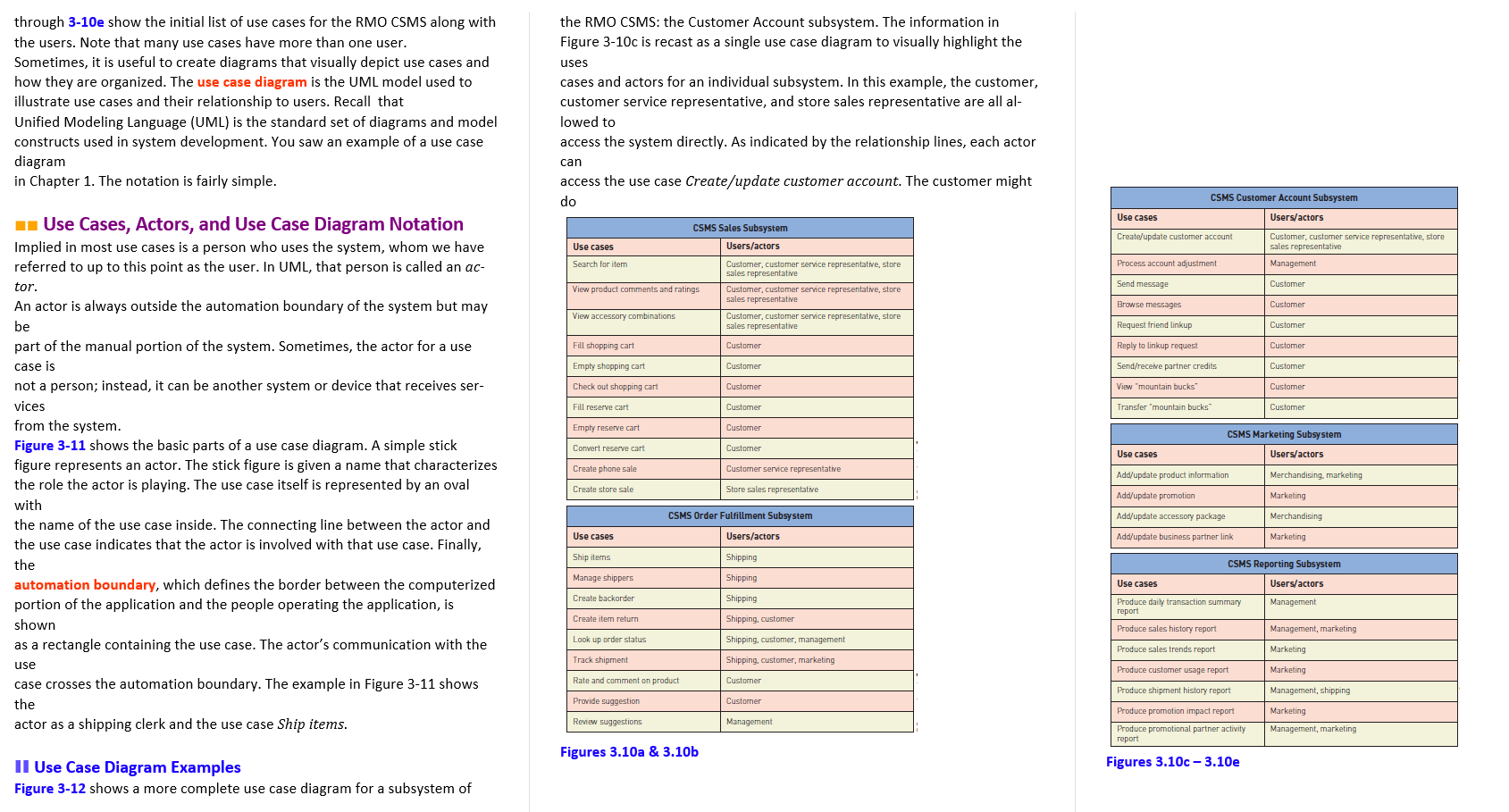
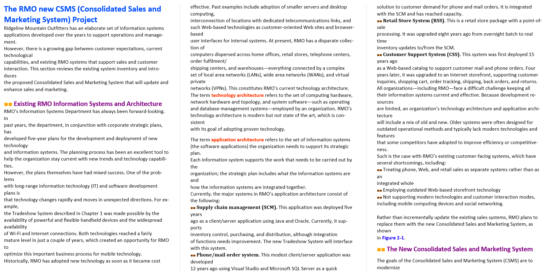
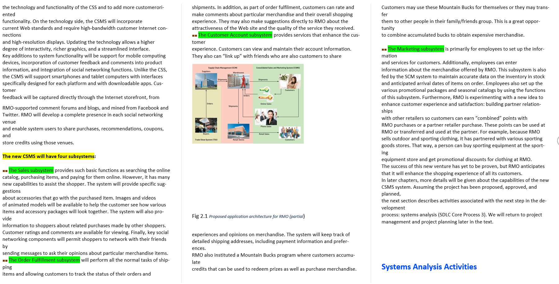
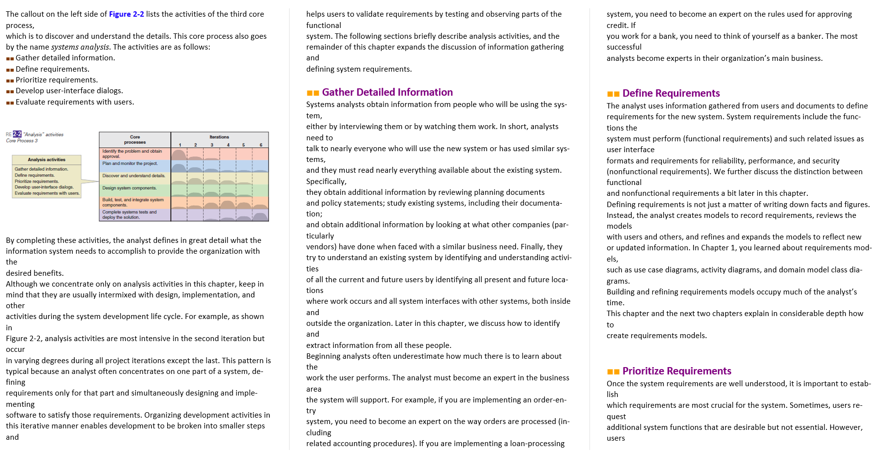
Use Cases in the "Ridgeline Mountain Outfit- ters" Case The RMO CSMS involves a variety of use cases, many of them just discussed. The analysts working on the new system have used all three techniques for identifying, validating, and refining use cases. The initial system vision (dis- cussed in Chapter 2) identified four subsystems: the Sales subsystem, the Order Fulfilment subsystem, the Customer Account subsystem, and the Market- ing subsystem. As work progressed, the analysts combined reports required by each subsystem into a fifth subsystem called the Reporting subsystem. In a sys- tem this size, the analyst should organize the use cases by subsystem to help track Use case Brief use case description Create customer account Look up customer User/actor enters new customer account data, and the system assigns account number, creates a customer record, and creates an account record. Useryactor enters customer account number, and the system retrieves and displays customer and account data. User/actor enters order number, and the system retrieves customer and order data; actor enters adjustment amount and the system creates a transaction record for the adjustment. Process account adjustment Figure 3.9 Use Cases and brief descriptions which subsystem is responsible for each use case. The analyst should also identify which use cases involve more than one type of user. It is important to recognize that this list of uses cases will continue to evolve as the project progresses. Additional use cases will be added, some might be eliminated, and some might be combined. It is helpful to immediately de- scribe some of the details of each use case, preferably in one sentence. This brief description is usually expanded to record more of the details when the de- velopers are designing and implementing the use case (see Chapter 5). Some exam- ples of brief use case descriptions are shown in Figure 3-9. Figures 3-10a the RMO CSMS: the Customer Account subsystem. The information in Figure 3-10c is recast as a single use case diagram to visually highlight the uses through 3-10e show the initial list of use cases for the RMO CSMS along with the users. Note that many use cases have more than one user. Sometimes, it is useful to create diagrams that visually depict use cases and how they are organized. The use case diagram is the UML model used to illustrate use cases and their relationship to users. Recall that Unified Modeling Language (UML) is the standard set of diagrams and model constructs used in system development. You saw an example of a use case diagram in Chapter 1. The notation is fairly simple. cases and actors for an individual subsystem. In this example, the customer, customer service representative, and store sales representative are all al- lowed to access the system directly. As indicated by the relationship lines, each actor can access the use case Create/update customer account. The customer might do CSMS Customer Account Subsystem Use cases Users/actors * Use Cases, Actors, and Use Case Diagram Notation Implied in most use cases is a person who uses the system, whom we have referred to up to this point as the user. In UML, that person is called an ac- CSMS Sales Subsystem Users/actors Create/update customer account Use cases Customer, customer service representative, store sales representative Management Search for item Process account adjustment tor. Send message Customer View product comments and ratings Customer, customer service representative, store sales representative Customer, customer service representative, store sales representative Customer customer service representative, store sales representative Browse messages Customer View accessory combinations An actor is always outside the automation boundary of the system but may be part of the manual portion of the system. Sometimes, the actor for a use Request friend linkup Customer Fill shopping cart Customer Reply to linkup request Customer case is Empty shopping cart Customer Send/receive partner credits Customer Check out shopping cart Customer View "mountain bucks Customer Fill reserve cart Customer Transfer mountain bucks Customer Empty reserve cart Customer Convert reserve cart Customer CSMS Marketing Subsystem Users/actors Use cases Create phone sale Customer service representative Add/update product information Merchandising, marketing Create store sale Store sales representative Add/update promotion Marketing Add/update accessory package Merchandising CSMS Order Fulfillment Subsystem Users/actors Use cases Add/update business partner link Marketing not a person; instead, it can be another system or device that receives ser- vices from the system. Figure 3-11 shows the basic parts of a use case diagram. A simple stick figure represents an actor. The stick figure is given a name that characterizes the role the actor is playing. The use case itself is represented by an oval with the name of the use case inside. The connecting line between the actor and the use case indicates that the actor is involved with that use case. Finally, the automation boundary, which defines the border between the computerized portion of the application and the people operating the application, is shown as a rectangle containing the use case. The actor's communication with the use case crosses the automation boundary. The example in Figure 3-11 shows the actor as a shipping clerk and the use case Ship items. Ship items Shipping Manage shippers Shipping CSMS Reporting Subsystem Users/actors Use cases Create backorder Shipping Management Create item return Shipping, customer Produce daily transaction summary report Produce sales history report Management, marketing Look up order status Shipping, customer, management Produce sales trends report Marketing Track shipment Shipping, customer, marketing Produce customer usage report Marketing Rate and comment on product Customer Provide suggestion Customer Produce shipment history report Produce promotion impact report Produce promotional partner activity Management, shipping Marketing Management, marketing Review suggestions Management report Figures 3.10a & 3.10b Figures 3.10c-3.10e Il Use Case Diagram Examples Figure 3-12 shows a more complete use case diagram for a subsystem of Sales Subsystem Fill Shopping Cart
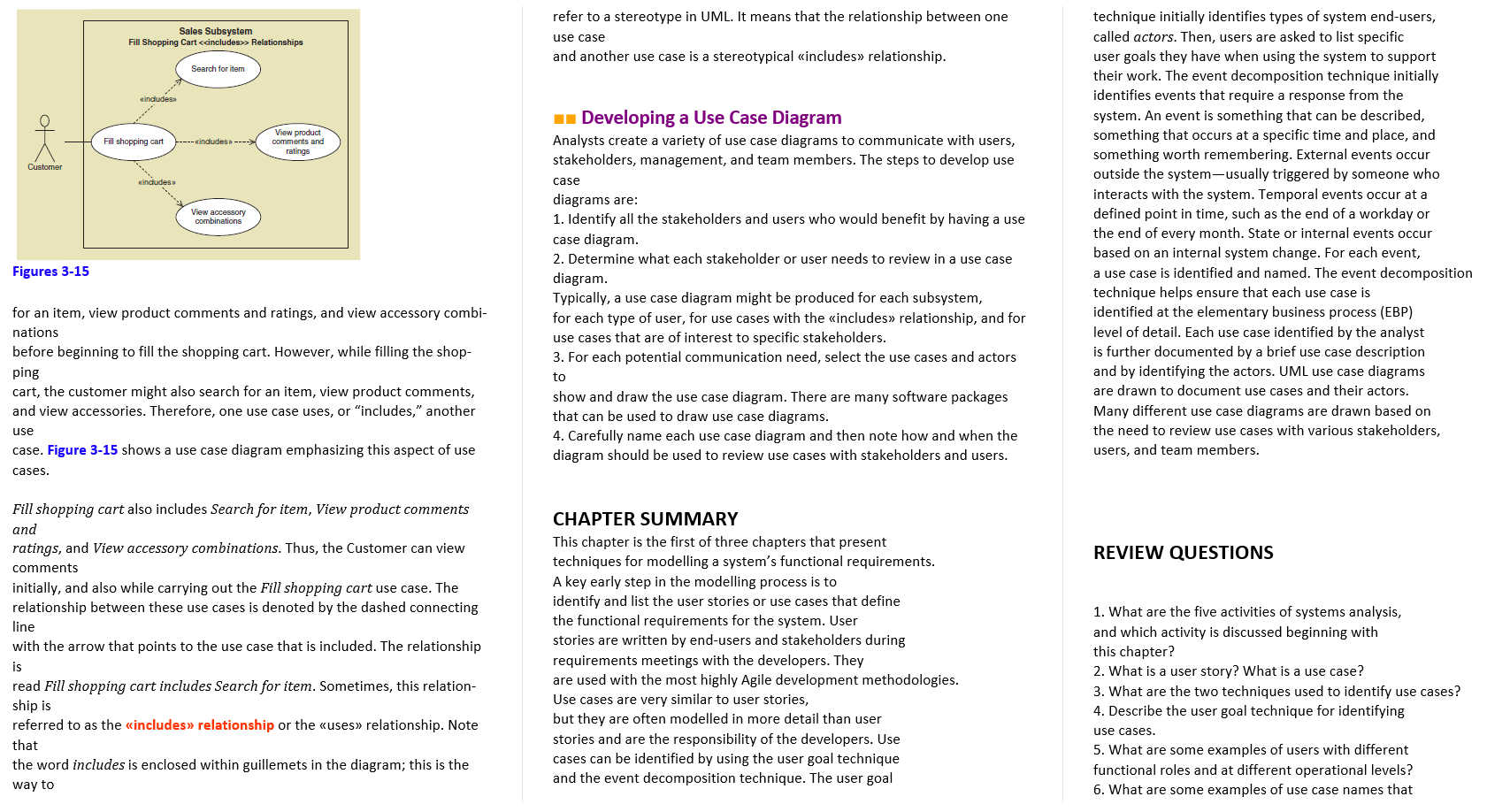
> Relationships refer to a stereotype in UML. It means that the relationship between one use case and another use case is a stereotypical includes relationship. Search for item eindudes ok Fill shopping cart ---- includes ----> View product comments and ratings Customer cincludes View accessory combinations technique initially identifies types of system end-users, called actors. Then, users are asked to list specific user goals they have when using the system to support their work. The event decomposition technique initially identifies events that require a response from the system. An event is something that can be described, something that occurs at a specific time and place, and something worth remembering. External events occur outside the system-usually triggered by someone who interacts with the system. Temporal events occur at a defined point in time, such as the end of a workday or the end of every month. State or internal events occur based on an internal system change. For each event, a use case is identified and named. The event decomposition technique helps ensure that each use case is identified at the elementary business process (EBP) level of detail. Each use case identified by the analyst is further documented by a brief use case description and by identifying the actors. UML use case diagrams are drawn to document use cases and their actors. Many different use case diagrams are drawn based on the need to review use cases with various stakeholders, users, and team members. 1 Developing a Use Case Diagram Analysts create a variety of use case diagrams to communicate with users, stakeholders, management, and team members. The steps to develop use case diagrams are: 1. Identify all the stakeholders and users who would benefit by having a use case diagram. 2. Determine what each stakeholder or user needs to review in a use case diagram. Typically, a use case diagram might be produced for each subsystem, for each type of user, for use cases with the includes relationship, and for use cases that are of interest to specific stakeholders. 3. For each potential communication need, select the use cases and actors to show and draw the use case diagram. There are many software packages that can be used to draw use case diagrams. 4. Carefully name each use case diagram and then note how and when the diagram should be used to review use cases with stakeholders and users. Figures 3-15 for an item, view product comments and ratings, and view accessory combi- nations before beginning to fill the shopping cart. However, while filling the shop- ping cart, the customer might also search for an item, view product comments, and view accessories. Therefore, one use case uses, or "includes," another use case. Figure 3-15 shows a use case diagram emphasizing this aspect of use cases. REVIEW QUESTIONS Fill shopping cart also includes Search for item, View product comments and ratings, and View accessory combinations. Thus, the Customer can view comments initially, and also while carrying out the Fill shopping cart use case. The relationship between these use cases is denoted by the dashed connecting line with the arrow that points to the use case that is included. The relationship is read Fill shopping cart includes Search for item. Sometimes, this relation- ship is referred to as the includes relationship or the uses relationship. Note that the word includes is enclosed within guillemets in the diagram; this is the way to CHAPTER SUMMARY This chapter is the first of three chapters that present techniques for modelling a system's functional requirements. A key early step in the modelling process is to identify and list the user stories or use cases that define the functional requirements for the system. User stories are written by end-users and stakeholders during requirements meetings with the developers. They are used with the most highly Agile development methodologies. Use cases are very similar to user stories, but they are often modelled in more detail than user stories and are the responsibility of the developers. Use cases can be identified by using the user goal technique and the event decomposition technique. The user goal 1. What are the five activities of systems analysis, and which activity is discussed beginning with this chapter? 2. What is a user story? What is a use case? 3. What are the two techniques used to identify use cases? 4. Describe the user goal technique for identifying use cases. 5. What are some examples of users with different functional roles and at different operational levels? 6. What are some examples of use case names that The RMO new CSMS (Consolidated Sales and Marketing System) Project Ridgeline Mountain Outfitters has an elaborate set of information systems applications developed over the years to support operations and manage- ment. However, there is a growing gap between customer expectations, current technological capabilities, and existing RMO systems that support sales and customer interaction. This section reviews the existing system inventory and intro- duces the proposed Consolidated Sales and Marketing System that will update and enhance sales and marketing. effective. Past examples include adoption of smaller servers and desktop computing, interconnection of locations with dedicated telecommunications links, and such Web-based technologies as customer-oriented Web sites and browser- based user interfaces for internal systems. At present, RMO has a disparate collec- tion of computers dispersed across home offices, retail stores, telephone centers, order fulfilment/ shipping centers, and warehouses-everything connected by a complex set of local area networks (LANs), wide area networks (WANs), and virtual private networks (VPNs). This constitutes RMO's current technology architecture. The term technology architecture refers to the set of computing hardware, network hardware and topology, and system software-such as operating and database management systems-employed by an organization. RMO's technology architecture is modern but not state of the art, which is con- sistent with its goal of adopting proven technology. Existing RMO Information Systems and Architecture RMO's Information Systems Department has always been forward-looking. In past years, the department, in conjunction with corporate strategic plans, has developed five-year plans for the development and deployment of new technology and information systems. The planning process has been an excellent tool to help the organization stay current with new trends and technology capabili- ties. However, the plans themselves have had mixed success. One of the prob- lems with long-range information technology (IT) and software development plans is that technology changes rapidly and moves in unexpected directions. For ex- ample, the Tradeshow System described in Chapter 1 was made possible by the availability of powerful and flexible handheld devices and the widespread availability of Wi-Fi and Internet connections. Both technologies reached a fairly mature level in just a couple of years, which created an opportunity for RMO to optimize this important business process for mobile technology. Historically, RMO has adopted new technology as soon as it became cost solution to customer demand for phone and mail orders. It is integrated with the SCM and has reached capacity. -- Retail Store System (RSS). This is a retail store package with a point-of- sale processing. It was upgraded eight years ago from overnight batch to real time inventory updates to/from the SCM. - Customer Support System (CSS). This system was first deployed 15 years ago as a Web-based catalog to support customer mail and phone orders. Four years later, it was upgraded to an Internet storefront, supporting customer inquiries, shopping cart, order tracking, shipping, back orders, and returns. All organizations including RMO-face a difficult challenge keeping all their information systems current and effective. Because development re- sources are limited, an organization's technology architecture and application archi- tecture will include a mix of old and new. Older systems were often designed for outdated operational methods and typically lack modern technologies and features that some competitors have adopted to improve efficiency or competitive- ness. Such is the case with RMO's existing customer-facing systems, which have several shortcomings, including: - Treating phone, Web, and retail sales as separate systems rather than as an integrated whole - Employing outdated Web-based storefront technology - Not supporting modern technologies and customer interaction modes, including mobile computing devices and social networking. The term application architecture refers to the set of information systems (the software applications) the organization needs to support its strategic plan. Each information system supports the work that needs to be carried out by the organization; the strategic plan includes what the information systems are and how the information systems are integrated together. Currently, the major systems in RMO's application architecture consist of the following: - Supply chain management (SCM). This application was deployed five years ago as a client/server application using Java and Oracle. Currently, it sup- ports inventory control, purchasing, and distribution, although integration of functions needs improvement. The new Tradeshow System will interface with this system. .. Phone/mail order system. This modest client/server application was developed 12 years ago using Visual Studio and Microsoft SQL Server as a quick Rather than incrementally update the existing sales systems, RMO plans to replace them with the new Consolidated Sales and Marketing System, as shown in Figure 2-1. 1 The New Consolidated Sales and Marketing System The goals of the Consolidated Sales and Marketing System (CSMS) are to modernize shipments. In addition, as part of order fulfilment, customers can rate and make comments about particular merchandise and their overall shopping experience. They may also make suggestions directly to RMO about the attractiveness of the Web site and the quality of the service they received. .. The Customer Account subsystem provides services that enhance the cus- tomer experience. Customers can view and maintain their account information. They also can "link up" with friends who are also customers to share Customers may use these Mountain Bucks for themselves or they may trans- fer them to other people in their family/friends group. This is a great oppor- tunity to combine accumulated bucks to obtain expensive merchandise. Supply Chain Management ISCHI Suppliers Consolidated Sales and Marketing System ICSHSI the technology and functionality of the CSS and to add more customerori- ented functionality. On the technology side, the CSMS will incorporate current Web standards and require high-bandwidth customer Internet con- nections and high-resolution displays. Updating the technology allows a higher degree of interactivity, richer graphics, and a streamlined interface. Key additions to system functionality will be support for mobile computing devices, incorporation of customer feedback and comments into product information, and integration of social networking functions. Unlike the CSS, the CSMS will support smartphones and tablet computers with interfaces specifically designed for each platform and with downloadable apps. Cus- tomer feedback will be captured directly through the Internet storefront, from RMO-supported comment forums and blogs, and mined from Facebook and Twitter. RMO will develop a complete presence in each social networking venue and enable system users to share purchases, recommendations, coupons, and store credits using those venues. Customers G. Orders Online Sales Shipments .. The Marketing subsystem is primarily for employees to set up the infor- mation and services for customers. Additionally, employees can enter information about the merchandise offered by RMO. This subsystem is also fed by the SCM system to maintain accurate data on the inventory in stock and anticipated arrival dates of items on order. Employees also set up the various promotional packages and seasonal catalogs by using the functions of this subsystem. Furthermore, RMO is experimenting with a new idea to enhance customer experience and satisfaction: building partner relation- ships with other retailers so customers can earn "combined" points with RMO purchases or a partner retailer purchase. These points can be used at RMO or transferred and used at the partner. For example, because RMO sells outdoor and sporting clothing, it has partnered with various sporting goods stores. That way, a person can buy sporting equipment at the sport- ing equipment store and get promotional discounts for clothing at RMO. The success of this new venture has yet to be proven, but RMO anticipates that it will enhance the shopping experience of all its customers. In later chapters, more details will be given about the capabilities of the new CSMS system. Assuming the project has been proposed, approved, and planned, the next section describes activities associated with the next step in the de- velopment process: systems analysis (SDLC Core Process 3). We will return to project management and project planning later in the text. Trade Show System ISSI Retail Stores Customers The new CSMS will have four subsystems: Fig 2.1 Proposed application architecture for RMO (partial) .. The Sales subsystem provides such basic functions as searching the online catalog, purchasing items, and paying for them online. However, it has many new capabilities to assist the shopper. The system will provide specific sug- gestions about accessories that go with the purchased item. Images and videos of animated models will be available to help the customer see how various items and accessory packages will look together. The system will also pro- vide information to shoppers about related purchases made by other shoppers. Customer ratings and comments are available for viewing. Finally, key social networking components will permit shoppers to network with their friends by sending messages to ask their opinions about particular merchandise items. -- The Order Fulfillment subsystem will perform all the normal tasks of ship- ping items and allowing customers to track the status of their orders and experiences and opinions on merchandise. The system will keep track of detailed shipping addresses, including payment information and prefer- ences. RMO also instituted a Mountain Bucks program where customers accumu- late credits that can be used to redeem prizes as well as purchase merchandise. Systems Analysis Activities The callout on the left side of Figure 2-2 lists the activities of the third core process, which is to discover and understand the details. This core process also goes by the name systems analysis. The activities are as follows: 1 Gather detailed information. Define requirements. Prioritize requirements. - Develop user-interface dialogs. Evaluate requirements with users. helps users to validate requirements by testing and observing parts of the functional system. The following sections briefly describe analysis activities, and the remainder of this chapter expands the discussion of information gathering and defining system requirements. system, you need to become an expert on the rules used for approving credit. If you work for a bank, you need to think of yourself as a banker. The most successful analysts become experts in their organization's main business. RE 2-2 "Analysis activities Core Process 3 Iterations 4 1 2 5 6 Core processes Identify the problem and obtain approval Plan and monitor the project. Analysis activities Gather detailed information. Define requirements Prioritize requirements Develop user interface dialogs. Evaluate requirements with users. Discover and understand details. Design system components. Build, test, and integrate system components. Complete systems tests and deploy the solution Gather Detailed Information Systems analysts obtain information from people who will be using the sys- tem, either by interviewing them or by watching them work. In short, analysts need to talk to nearly everyone who will use the new system or has used similar sys- tems, and they must read nearly everything available about the existing system. Specifically, they obtain additional information by reviewing planning documents and policy statements; study existing systems, including their documenta- tion; and obtain additional information looking at what other companies (par- ticularly vendors) have done when faced with a similar business need. Finally, they try to understand an existing system by identifying and understanding activi- ties of all the current and future users by identifying all present and future loca- tions where work occurs and all system interfaces with other systems, both inside and outside the organization. Later in this chapter, we discuss how to identify and extract information from all these people. Beginning analysts often underestimate how much there is to learn about the work the user performs. The analyst must become an expert in the business area the system will support. For example, if you are implementing an order-en- try system, you need to become an expert on the way orders are processed (in- cluding related accounting procedures). If you are implementing a loan-processing 1 Define Requirements The analyst uses information gathered from users and documents to define requirements for the new system. System requirements include the func- tions the system must perform (functional requirements) and such related issues as user interface formats and requirements for reliability, performance, and security (nonfunctional requirements). We further discuss the distinction between functional and nonfunctional requirements a bit later in this chapter. Defining requirements is not just a matter of writing down facts and figures. Instead, the analyst creates models to record requirements, reviews the models with users and others, and refines and expands the models to reflect new or updated information. In Chapter 1, you learned about requirements mod- els, such as use case diagrams, activity diagrams, and domain model class dia- grams. Building and refining requirements models occupy much of the analyst's time. This chapter and the next two chapters explain in considerable depth how to create requirements models. By completing these activities, the analyst defines in great detail what the information system needs to accomplish to provide the organization with the desired benefits. Although we concentrate only on analysis activities in this chapter, keep in mind that they are usually intermixed with design, implementation, and other activities during the system development life cycle. For example, as shown in Figure 2-2, analysis activities are most intensive in the second iteration but occur in varying degrees during all project iterations except the last. This pattern is typical because an analyst often concentrates on one part of a system, de- fining requirements only for that part and simultaneously designing and imple- menting software to satisfy those requirements. Organizing development activities in this iterative manner enables development to be broken into smaller steps and 1 Prioritize Requirements Once the system requirements are well understood, it is important to estab- lish which requirements are most crucial for the system. Sometimes, users re- quest additional system functions that are desirable but not essential. However, users and analysts need to ask themselves which functions are truly important and which are fairly important but not absolutely required. Again, an analyst who understands the organization and the work done by the users will have more insight toward answering these questions. Why prioritize the functions requested by the users? Resources are always limited, and the analyst must always be prepared to justify the scope of the system. Therefore, it is important to know what is absolutely required. Unless the analyst carefully evaluates priorities, system requirements tend to expand based on user input, but it is often difficult for users to interpret and vali- date such abstract models. In comparison, user validation of a user interface is much simpler and more reliable because the user can see and feel the system. To most users, the user interface is all that matters. Thus, developing user-interface dialogs is a powerful method of eliciting and documenting requirements. Analysts can develop user interfaces via abstract models, such as interaction diagrams and written dia- logs (covered in more detail in later chapters), or they can develop storyboards the system will include new or innovative technology, the users may need help visualizing the possibilities available from the new technology as they define what they require. Prototypes can fill that need. The processes of eliciting require- ments, building models and prototypes, and evaluating them with users may repeat many times until requirements models and prototypes are complete and accurate. as 1 The Stakeholders for RMO As a starting point for identifying CSMS stakeholders, it is helpful to develop or a users make more suggestions (a phenomenon called scope creep). Require- ments priorities also help to determine the number, composition, and ordering of project iterations. High-priority requirements are often incorporated into early pro- ject iterations so analysts and users have ample opportunity to refine those parts of the system. Furthermore, a project with many high-priority requirements will typically have many iterations. user-interface prototypes on the actual input/output devices that users will use (e.g., a computer monitor, iPad, or smartphone). A prototype interface can serve as a requirement and a starting point for developing a portion of the system. A user-interface prototype developed in an early iteration can be expanded in later iterations to become a fully functioning part of the system. Develop User-Interface Dialogs In some cases, when a new system is replacing an old system that does simi- lar work, users are usually quite sure about their requirements and the desired form of the user interface. In other cases, the system development project breaks new ground by automating functions that were previously performed manually or by implementing functions that were not performed in the past. In either case, users tend to be uncertain of many aspects of system requirements. Such require- ments models as use cases, activity diagrams, and interaction diagrams can be de- veloped 1 Evaluate Requirements with Users Ideally, evaluating requirements with users and documenting the require- ments are fully integrated. But in practice, users generally have other responsibilities besides developing a new system. Thus, analysts usually use an iterative process in which they elicit user input to model requirements, return to the user for addi- tional input or validation, and then work alone to incorporate the new input and refine the models. Prototypes of user interfaces and other parts of the system may also be developed when "paper" models are inadequate or when users and analysts need to prove that chosen technologies will do what they are supposed to do. Also, if list of current CSS stakeholders, which include: u. Phone/mail sales order representatives Warehouse and shipping personnel -- Marketing personnel who maintain online catalog information - Marketing, sales, accounting, and financial managers 1 Senior executives 1 Customers - External shippers (e.g., UPS and FedEx) Because the CSMS will take over existing functions of the CSS, the list of CSMS stakeholders includes all the stakeholders in the CSS list; however, there are some subtle differences. For example, the inclusion of social networking functions in the CSMS and the planned ability to share Mountain Bucks expands the defini- tion of a customer. Whereas the old CSS was intended for use by potential custom- ers visiting the Web site, the new system will interact with a much larger group of ex- ternal stakeholders, including friends and family of existing customers and poten- tially all users of popular social networking sites. In essence, the stakeholder group "Customers" is much larger, more diverse, and includes people who have not purchased


