

Question: Assignment Altera Board The Altera board is a programmable FPGA device with a variety of lI/O components. For now, we're just going use some of
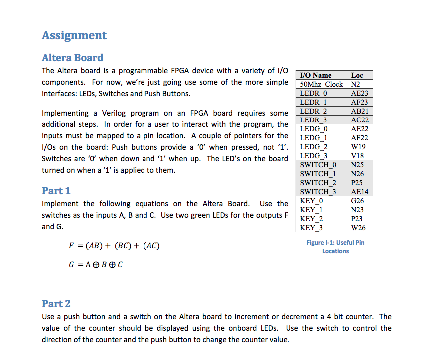
Assignment Altera Board The Altera board is a programmable FPGA device with a variety of lI/O components. For now, we're just going use some of the more simple 50Mhz Clock N2 interfaces: LEDs, Switches and Push Buttons VO Name Loc LEDR 0 LEDR 1 AE23 AF23 AB21 AC22 AE22 AF22 Implementing a Verilog program on an FPGA board requires some LEDR 2 additional steps. In order for a user to interact with the program, the inputs must be mapped to a pin location. A couple of pointers for the LEDG I I/Os on the board: Push buttons provide a '0' when pressed, not '1'. LEDG Switches are o when down and 1' when up. The LED's on the board LEDG 3 turned on when a '1' is applied to them LEDR 3 LEDG 0 2W19 V18 SWITCH 0 N25 SWITCH 1 N26 SWITCH 2 P25 SWITCH 3 AE14 KEY 0 Part 1 Implement the following equations on the Altera Board. Use the switches as the inputs A, B and C. Use two green LEDs for the outputs F and G G26 N23 P23 W26 KEY 2 KEY 3 F = (AB) + (BC) + (AC) Figure -1: Useful Pin Locations Part 2 Use a push button and a switch on the Altera board to increment or decrement a 4 bit counter. The value of the counter should be displayed using the onboard LEDs. Use the switch to control the direction of the counter and the push button to change the counter value Assignment Altera Board The Altera board is a programmable FPGA device with a variety of lI/O components. For now, we're just going use some of the more simple 50Mhz Clock N2 interfaces: LEDs, Switches and Push Buttons VO Name Loc LEDR 0 LEDR 1 AE23 AF23 AB21 AC22 AE22 AF22 Implementing a Verilog program on an FPGA board requires some LEDR 2 additional steps. In order for a user to interact with the program, the inputs must be mapped to a pin location. A couple of pointers for the LEDG I I/Os on the board: Push buttons provide a '0' when pressed, not '1'. LEDG Switches are o when down and 1' when up. The LED's on the board LEDG 3 turned on when a '1' is applied to them LEDR 3 LEDG 0 2W19 V18 SWITCH 0 N25 SWITCH 1 N26 SWITCH 2 P25 SWITCH 3 AE14 KEY 0 Part 1 Implement the following equations on the Altera Board. Use the switches as the inputs A, B and C. Use two green LEDs for the outputs F and G G26 N23 P23 W26 KEY 2 KEY 3 F = (AB) + (BC) + (AC) Figure -1: Useful Pin Locations Part 2 Use a push button and a switch on the Altera board to increment or decrement a 4 bit counter. The value of the counter should be displayed using the onboard LEDs. Use the switch to control the direction of the counter and the push button to change the counter value
Step by Step Solution
There are 3 Steps involved in it

Get step-by-step solutions from verified subject matter experts