

Question: Assignment Instructions: 1) Consider the instruction slt, which has the format: slt $rd, $rs, $rt. a. The instruction sets $rd to 1 if and only
Assignment Instructions:
1) Consider the instruction slt, which has the format: slt $rd, $rs, $rt.
a. The instruction sets $rd to 1 if and only if $
i. Provide an informal RTL (register transfer language) describing the instruction semantics
ii. Explain the way that the instruction is mapped into Figure 4.24 from the book by Patterson (below).
2) Consider the instruction slti, which has the format: slti $rt, $rs, constant.
a. The instruction sets $rt to 1 if and only if $
i. Provide an informal RTL (register transfer language) describing the instruction semantics
ii. Explain the way that the instruction is mapped into Figure 4.24 from the book by Patterson (below).
3) Consider the pseudo instruction b, which has the format: b label. The instruction performs an un-conditional branch relative to PC to the label specified in the instruction. Since this is a pseudo instruction, the assembler first convert it into a real instruction using beq.
i. Provide an informal RTL (register transfer language) describing the instruction semantics
ii. Explain the way that the instruction is mapped into Figure 4.24 from the book by Patterson (below).
4) Consider the instruction lw which has the format: lw $rt, offset($rs). The instruction loads the contents the memory address pointed to by $rs+offset into the register $rt.
i. Provide an informal RTL (register transfer language) describing the instruction semantics
ii. Explain the way that the instruction is mapped into Figure 4.24from the book by Patterson (below).
5) Consider the instruction jal, which has the format: jal label.
a. The instruction can be used to implement a function call.
i. Provide an informal RTL (register transfer language) describing the instruction semantics
ii. Explain the way that the instruction should be mapped into a modified version of Figure 4.24 from the book by Patterson (below). You can assume the availability of a control line jal and a micro instruction of the form: RF[31]
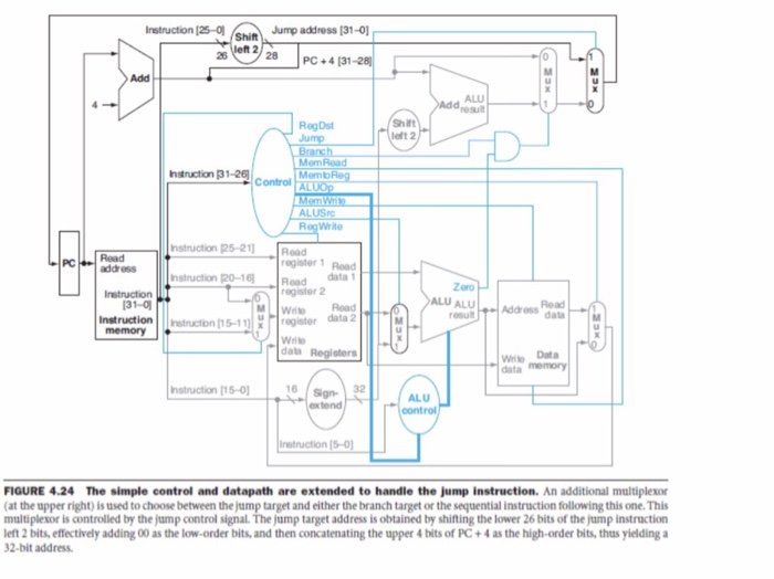
Shif Jump address (31- left 2 Instruction (25-0 26 28 PC+4131-28 Add ALU RegDst Shift Mom Read Mem Intruction 31-26 Control RegWrite register 1 Road egister 2 nstruction 25-211Road address nstruction po-16] |Road -data 1 Zero LU ALUss da Instruction 31-0 Instruction Instucon (15-11 memory resul register data 2 Wite data Registers data memory 16 sign Sign- 32 extend Instruction [15-0 ALU control Instruction (5-01 FIGURE 4.24 The simple control and datapath are extended to handle the jump instruction. An additional multiplexor (at the upper right) is used to choose between the jump target and either the branch target or the sequential instruction following this one. This multiplexor is controlled by the jump control signal. The jump target address is obtained by shifting the lower 26 bits of the jump instruction left 2 bits, effectively adding 00 as the low-order bits, and then concatenating the upper 4 bits of PC +4 as the high-order bits, thus yielding a 32-bit address Shif Jump address (31- left 2 Instruction (25-0 26 28 PC+4131-28 Add ALU RegDst Shift Mom Read Mem Intruction 31-26 Control RegWrite register 1 Road egister 2 nstruction 25-211Road address nstruction po-16] |Road -data 1 Zero LU ALUss da Instruction 31-0 Instruction Instucon (15-11 memory resul register data 2 Wite data Registers data memory 16 sign Sign- 32 extend Instruction [15-0 ALU control Instruction (5-01 FIGURE 4.24 The simple control and datapath are extended to handle the jump instruction. An additional multiplexor (at the upper right) is used to choose between the jump target and either the branch target or the sequential instruction following this one. This multiplexor is controlled by the jump control signal. The jump target address is obtained by shifting the lower 26 bits of the jump instruction left 2 bits, effectively adding 00 as the low-order bits, and then concatenating the upper 4 bits of PC +4 as the high-order bits, thus yielding a 32-bit address
Step by Step Solution
There are 3 Steps involved in it

Get step-by-step solutions from verified subject matter experts