

Question: BACKGROUND: QUESTION: 2. The block diagram below represents a system that is being designed. A temperature sensor measures the temperature of a process. The output
BACKGROUND:

QUESTION:

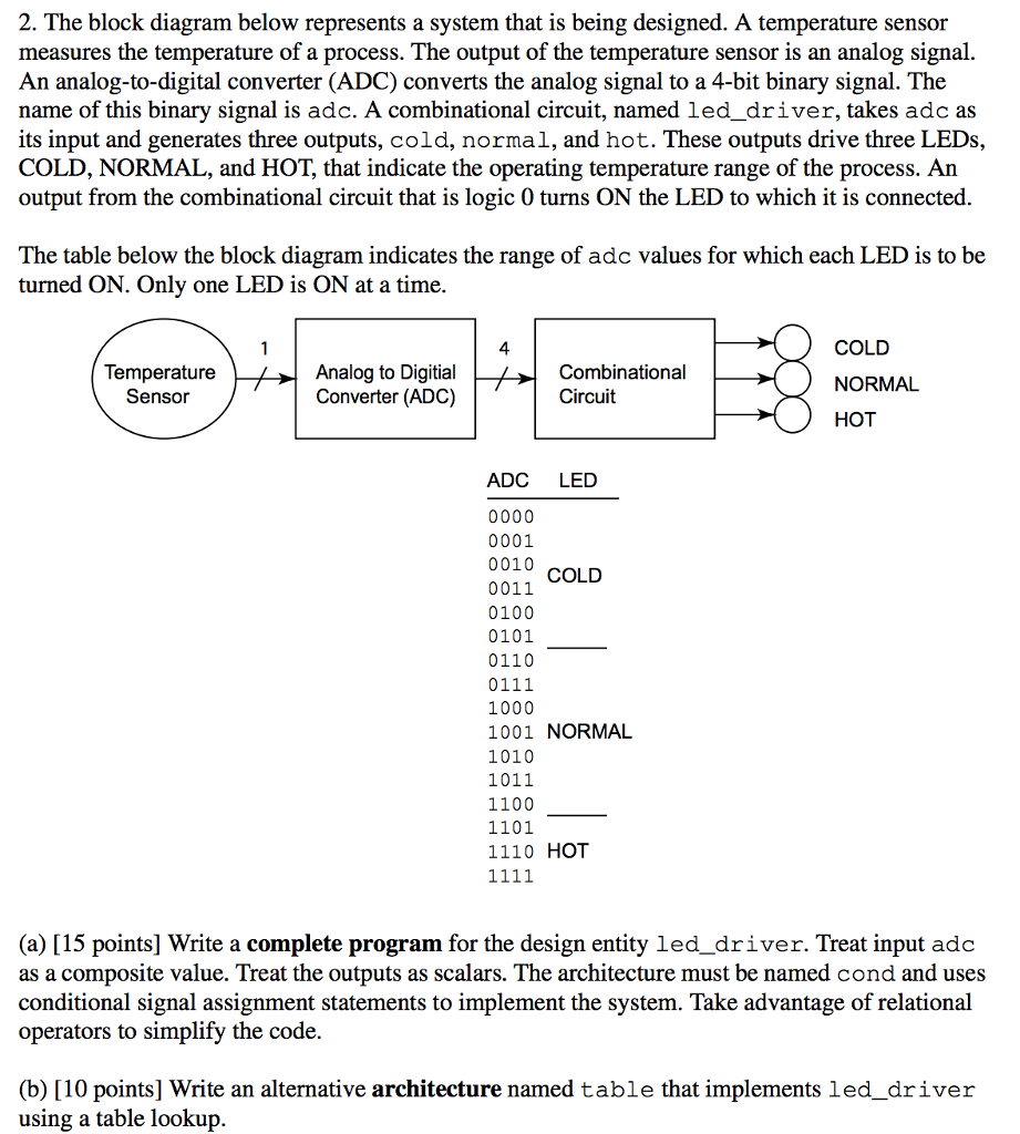
2. The block diagram below represents a system that is being designed. A temperature sensor measures the temperature of a process. The output of the temperature sensor is an analog signal An analog-to-digital converter (ADC converts the analog signal to a 4-bit binary signal. The name of this binary signal is adc. A combinational circuit, named led driver, takes adc as its input and generates three outputs, cold, normal, and hot. These outputs drive three LEDs, COLD, NORMAL, and HOT that indicate the operating temperature range of the process. An output from the combinational circuit that is logic 0 turns ON the LED to which it is connected. The table below the block diagram indicates the range of ado values for which each LED is to be turned ON. Only one LED is ON at a time. COLD Temperature Analog to Digitial Combinational NORMAL Sensor Converter (ADC) Circuit HOT ADC LED 0000 0001 0010 COLD 0011 0100 0101 0110 0111 1000 1001 NORMAL 1010 1011 1100 1101 1110 HOT (a) [15 points] Write a complete program for the design entity led driver. Treat input adc as a composite value. Treat the outputs as scalars. The architecture must be named cond and uses conditional signal assignment statements to implement the system. Take advantage of relational operators to simplify the code. (b) [10 points] Write an alternative architecture named table that implements led driver using a table lookup 2. The block diagram below represents a system that is being designed. A temperature sensor measures the temperature of a process. The output of the temperature sensor is an analog signal An analog-to-digital converter (ADC converts the analog signal to a 4-bit binary signal. The name of this binary signal is adc. A combinational circuit, named led driver, takes adc as its input and generates three outputs, cold, normal, and hot. These outputs drive three LEDs, COLD, NORMAL, and HOT that indicate the operating temperature range of the process. An output from the combinational circuit that is logic 0 turns ON the LED to which it is connected. The table below the block diagram indicates the range of ado values for which each LED is to be turned ON. Only one LED is ON at a time. COLD Temperature Analog to Digitial Combinational NORMAL Sensor Converter (ADC) Circuit HOT ADC LED 0000 0001 0010 COLD 0011 0100 0101 0110 0111 1000 1001 NORMAL 1010 1011 1100 1101 1110 HOT (a) [15 points] Write a complete program for the design entity led driver. Treat input adc as a composite value. Treat the outputs as scalars. The architecture must be named cond and uses conditional signal assignment statements to implement the system. Take advantage of relational operators to simplify the code. (b) [10 points] Write an alternative architecture named table that implements led driver using a table lookup
Step by Step Solution
There are 3 Steps involved in it

Get step-by-step solutions from verified subject matter experts