

Question: Basic dimensions and a solid model of a bicycle brake lever are shown in Figs. E1-4 (a) and (b). The brake lever is subject
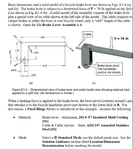
Basic dimensions and a solid model of a bicycle brake lever are shown in Figs. E1-4 (a) and (b). The brake lever is subject to a downward force of F = 70-lb applied on the Split Line shown in Fig. El-4 (b). A solid model of the assembly consists of the brake lever plus a partial view of its cable shown at the left side of the model. The cable connects to caliper brakes at either the front or rear bicycle wheel; only a "stub" length of the cable is shown. Open the file Brake Lever Assembly 1-4. 3500 1.75 35 0.375 2 1.375 0.75 Mesh: 4.50 413- 09 A Cable F = 70 lb Brake lever pivot. The handlebar pivot is not shown. (a) (b) Figure E1-4 - Dimensioned view of brake lever and solid model view showing external load applied to a split line. (All dimensions in inches.) When a braking force is applied to the brake lever, the lever pivots (rotates) around a pin that attaches it to the bicycle handlebar pivot (not shown) at the lower hole at A. For this reason, a Fixed Hinge fixture is introduced in this example. Assume the following: Material: Brake lever - Aluminum, 201.0-T7 Insulated Mold Casting (SS) Cable & Cable Anchor Steel, AISI 347 Annealed Stainless Steel (SS) Select a Standard Mesh; use the default mesh size. See the Solution Guidance section titled Location/Dimension Determination before meshing the model.
Step by Step Solution
There are 3 Steps involved in it
Solutions Step 1 The image you shared seems to be related to calculating the bending stress on certa... View full answer

Get step-by-step solutions from verified subject matter experts