

Question: BINARY COUNTER - PLEASE solve in Logisim software POWER POWER OUTPUT LEDS SWITCH PIN (MR) Q30201120 MR' VCC o B VCC o o o CP
BINARY COUNTER - PLEASE solve in Logisim software
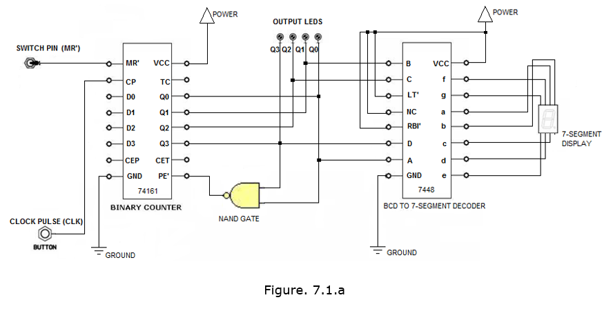
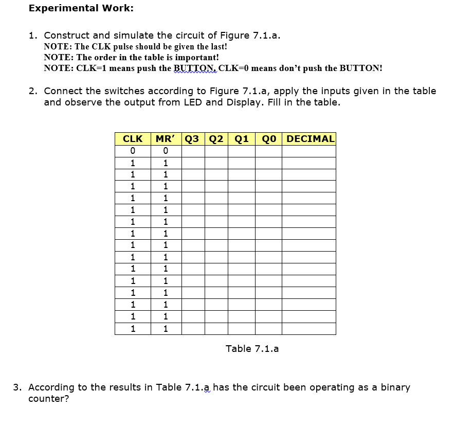
POWER POWER OUTPUT LEDS SWITCH PIN (MR") Q30201120 MR' VCC o B VCC o o o CP TC o f o o o o o DO QO o O LT g o D1 Q1 o NC o 66 o D2 Q2 o RBI b O 7-SEGMENT DISPLAY o D3 Q3 o O D o O CEP d o GND PE GND e 74161 7448 BCD TO 7-SEGMENT DECODER BINARY COUNTER CLOCK PUL SE (CLK) NAND GATE BUTTON GROUND GROUND Figure. 7.1.a Experimental Work: 1. Construct and simulate the circuit of Figure 7.1.a. NOTE: The CLK pulse should be given the last! NOTE: The order in the table is important! NOTE: CLK=1 means push the BUTTON, CLK=0 means don't push the BUTTON! 2. Connect the switches according to Figure 7.1.a, apply the inputs given in the table and observe the output from LED and Display. Fill in the table. QO DECIMAL CLK 0 1 1 1 1 1 1 1 1 1 1 1 1 1 1 1 MR' Q3 Q2 Q1 0 1 1 1 1 1 1 1 1 1 1 1 1 1 1 1 Table 7.1.a 3. According to the results in Table 7.1.a has the circuit been operating as a binary counter
Step by Step Solution
There are 3 Steps involved in it

Get step-by-step solutions from verified subject matter experts