

Question: C.1. In this experiment, there are 4-bit binary Input X4X3X2X1 and 4-bit for the Output Y4Y3Y2Y1. C.2. Draw the circuit on LogicWorks from output equations
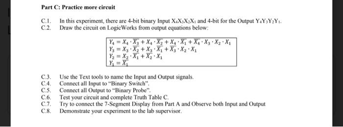
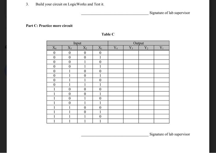
C.1. In this experiment, there are 4-bit binary Input X4X3X2X1 and 4-bit for the Output Y4Y3Y2Y1. C.2. Draw the circuit on LogicWorks from output equations below: Y4=X4X3+X4X2+X4X1+X4X3X2X1Y3=X3X2+X3X1+X3X2X1Y2=X2X1+X2X1Y1=X1 C.3. Use the Text tools to name the Input and Output signals. C.4. Connect all Input to "Binary Switch". C.5. Connect all Output to "Binary Probe". C.6. Test your circuit and complete Truth Table C. C.7. Try to connect the 7-Segment Display from Part A and Observe both Input and Output C.8. Demonstrate your experiment to the lab supervisor. 3. Build your circuit on LogicWorks and Test it. Signature of lab supervisor Part C: Practice more circuit Table C Signature of lab supervisor
Step by Step Solution
There are 3 Steps involved in it

Get step-by-step solutions from verified subject matter experts