

Question: Can anyone create a logic diagram (using AND gates) for this truth table of a 4 to 16 decoder? E stands for Enable which is
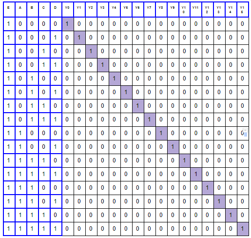
Can anyone create a logic diagram (using AND gates) for this truth table of a 4 to 16 decoder? E stands for Enable which is a typical additional input of a decoder. You can use a program called logisim to design it. Thanks in advance! Note: Please do NOT design this with 3-8 decoders. Just wires, AND gates, and the 4(5) inputs are enough. Thanks again :)
1 0 0 01 0 1 0 00 0 0 0 0 0 00 0 0 0 0 1 0 0 10 0 0 1 00 0 0 0 0 0 00 0 0 0 0 1 0 0 11 0 0 0 10 0 0 0 0 0 00 0 0 0 0 1 0 1 00 0 0 0 01 0 0 0 0 0 00 0 0 0 0 1 0 1 10 0 0 0 00 0 1 0 0 0 00 0 0 0 0 1 0 1 11 0 0 0 00 0 0 1 0 0 00 0 0 0 0 1 1 0 0 0 00 00 00 0 0 1 0 0 0 0 0 0 0 110 01 0 0 0 00 0 0 0 0 1 00 0 0 0 0 111 10 0 0 0 00 0 0 0 0 0 10 0 0 0 0 111 11 0 0 0 00 0 0 0 0 0 0 1 0 0 0 0 111 00 0 0 0 00 0 0 0 0 0 00 1 0 0 0 111 01 0 0 0 00 0 0 0 0 0 00 0 1 0 0 111 10 0 0 0 00 0 0 0 0 0 00 0 0 1 0 1 1 1 11 0 0 0 00 0 0 0 0 0 0 0 0 0 0 1 1 0 0 01 0 1 0 00 0 0 0 0 0 00 0 0 0 0 1 0 0 10 0 0 1 00 0 0 0 0 0 00 0 0 0 0 1 0 0 11 0 0 0 10 0 0 0 0 0 00 0 0 0 0 1 0 1 00 0 0 0 01 0 0 0 0 0 00 0 0 0 0 1 0 1 10 0 0 0 00 0 1 0 0 0 00 0 0 0 0 1 0 1 11 0 0 0 00 0 0 1 0 0 00 0 0 0 0 1 1 0 0 0 00 00 00 0 0 1 0 0 0 0 0 0 0 110 01 0 0 0 00 0 0 0 0 1 00 0 0 0 0 111 10 0 0 0 00 0 0 0 0 0 10 0 0 0 0 111 11 0 0 0 00 0 0 0 0 0 0 1 0 0 0 0 111 00 0 0 0 00 0 0 0 0 0 00 1 0 0 0 111 01 0 0 0 00 0 0 0 0 0 00 0 1 0 0 111 10 0 0 0 00 0 0 0 0 0 00 0 0 1 0 1 1 1 11 0 0 0 00 0 0 0 0 0 0 0 0 0 0 1
Step by Step Solution
There are 3 Steps involved in it

Get step-by-step solutions from verified subject matter experts