

Question: can I get some help how to write an assembly code for this work? Yes... How can I simulate without hex code, thats what I
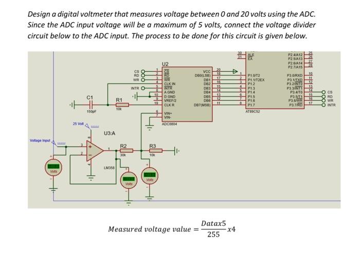
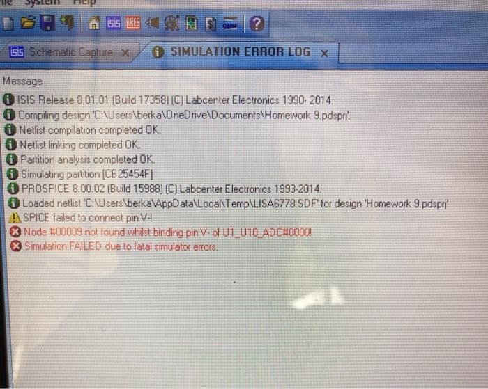
Design a digital voltmeter that measures voltage between 0 and 20 volts using the ADC. Since the ADC input voltage will be a maximum of 5 volts, connect the voltage divider circuit below to the ADC input. The process to be done for this circuit is given below. U2 P2412 P2 SIT) P2 GA14 P2.TIA15 CS RD WRO 10 17 16 P1/T2 P11/T2EX P12 PAS PE 4 INTRO VCC 08013 DBT DE2 DAS D84 DOS 086 (MSB) 14 PORXD 2 MB P32TO PANTE P311 P36 WR POTRD C1 11 WR CLK IN INTE A GND DOND VREF: 2 CUKR VIN. VIN ADC0004 R1 PES 12 111 PEG 15 17 OCs ORO O WR O INTR PAT 10% 150pF AT89C52 25 Volt U3:A Vortage Input R2 R3 30 TOR LM350 Datax5 Measured voltage value = 255 x4 A bor ? isis Schematie Capture X SIMULATION ERROR LOG X Message ISIS Release 8.01.01 (Build 17358) (C) Labcenter Electronics 1990- 2014. Compiling design 'C:\Users\berka\OneDrive Documents\Homework 9 pdspri Netlist compilation completed OK. Netlist linking completed OK. Partition analysis completed OK. Simulating partition (CB25454F] PROSPICE 8.00.02 (Build 15988) (C) Labcenter Electronics 1993-2014. Loaded netlist 'C:\Users\berka\AppData\Local\Temp\LISA6778. SDF' for design 'Homework 9. pdspri" SPICE failed to connect pin VI Node #00009 not found whilst binding pin V of U1_U10_ADCHO0001 % Simulation FAILED due to fetal simulator errors
Step by Step Solution
There are 3 Steps involved in it

Get step-by-step solutions from verified subject matter experts