

Question: Circuit 1: Design a four-bit arithmetic logic unit (ALU) connected with an 8 x 9 memory. The circuit has two four-bit input data paths (AO,
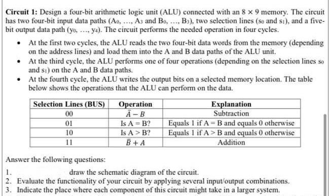
Circuit 1: Design a four-bit arithmetic logic unit (ALU) connected with an 8 x 9 memory. The circuit has two four-bit input data paths (AO, .... Az and Bo..... Bs), two selection lines (so and si), and a five- bit output data path (yo, ..., y). The circuit performs the needed operation in four cycles. At the first two cycles, the ALU reads the two four-bit data words from the memory (depending on the address lines) and load them into the A and B data paths of the ALU unit. At the third cycle, the ALU performs one of four operations (depending on the selection lines so and st) on the A and B data paths. At the fourth cycle, the ALU writes the output bits on a selected memory location. The table below shows the operations that the ALU can perform on the data. Selection Lines (BUS) Operation Explanation 00 A-B Subtraction 01 Is A = B2 Equals 1 if A= B and equals 0 otherwise 10 Is A > B? Equals 1 if A> B and cquals 0 otherwise 11 B +A Addition Answer the following questions: 1. draw the schematic diagram of the circuit 2. Evaluate the functionality of your circuit by applying several input/output combinations. 3. Indicate the place where cach component of this circuit might take in a larger system
Step by Step Solution
There are 3 Steps involved in it

Get step-by-step solutions from verified subject matter experts