

Question: Complete a single cycle data path and control table for the following ARM v7 instruction. The ADD instruction takes a value from the genetal-purpose register
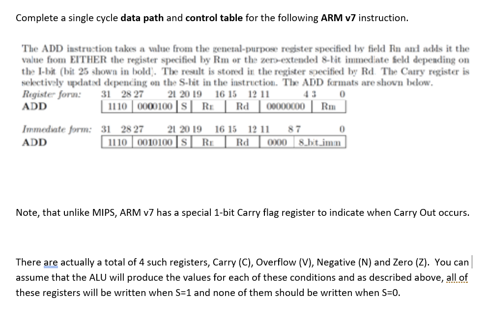
Complete a single cycle data path and control table for the following ARM v7 instruction. The ADD instruction takes a value from the genetal-purpose register specified by field Rn and adds it the value fiom EITHER the register specified by Rm or the zero-extendel 8-lit immediate feld depeading on the I-bit (bit 25 shown in bold. The resilt is stored in the register secified by Rd The Carry register is sekctively updatod depencing on the S-hit in the instructio. The ADD formats are shovn blow. Register form: 2827 2019 1615 12 11 ADD 43 1110|0001001 SI RE ? Rd 00000001 Rm mmedate form: 31 2827 21 20 19 16 15 12 11 87 ADD 0 1110 0010100 SRERd 0000 8 hit.im Note, that unlike MIPS, ARM v7 has a special 1-bit Carry flag register to indicate when Carry Out occurs. There are actually a total of 4 such registers, Carry (C), Overflow (V), Negative (N) and Zero (Z). You can assume that the ALU will produce the values for each of these conditions and as described above, all of these registers will be written when S-1 and none of them should be written when S-0. Complete a single cycle data path and control table for the following ARM v7 instruction. The ADD instruction takes a value from the genetal-purpose register specified by field Rn and adds it the value fiom EITHER the register specified by Rm or the zero-extendel 8-lit immediate feld depeading on the I-bit (bit 25 shown in bold. The resilt is stored in the register secified by Rd The Carry register is sekctively updatod depencing on the S-hit in the instructio. The ADD formats are shovn blow. Register form: 2827 2019 1615 12 11 ADD 43 1110|0001001 SI RE ? Rd 00000001 Rm mmedate form: 31 2827 21 20 19 16 15 12 11 87 ADD 0 1110 0010100 SRERd 0000 8 hit.im Note, that unlike MIPS, ARM v7 has a special 1-bit Carry flag register to indicate when Carry Out occurs. There are actually a total of 4 such registers, Carry (C), Overflow (V), Negative (N) and Zero (Z). You can assume that the ALU will produce the values for each of these conditions and as described above, all of these registers will be written when S-1 and none of them should be written when S-0
Step by Step Solution
There are 3 Steps involved in it

Get step-by-step solutions from verified subject matter experts