

Question: Consider a three-phase four-wire grounded distribution overhead line where the coordinates of the three phases and the neutral conductor are specified as below (the
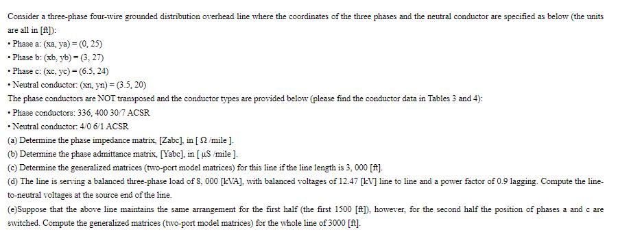
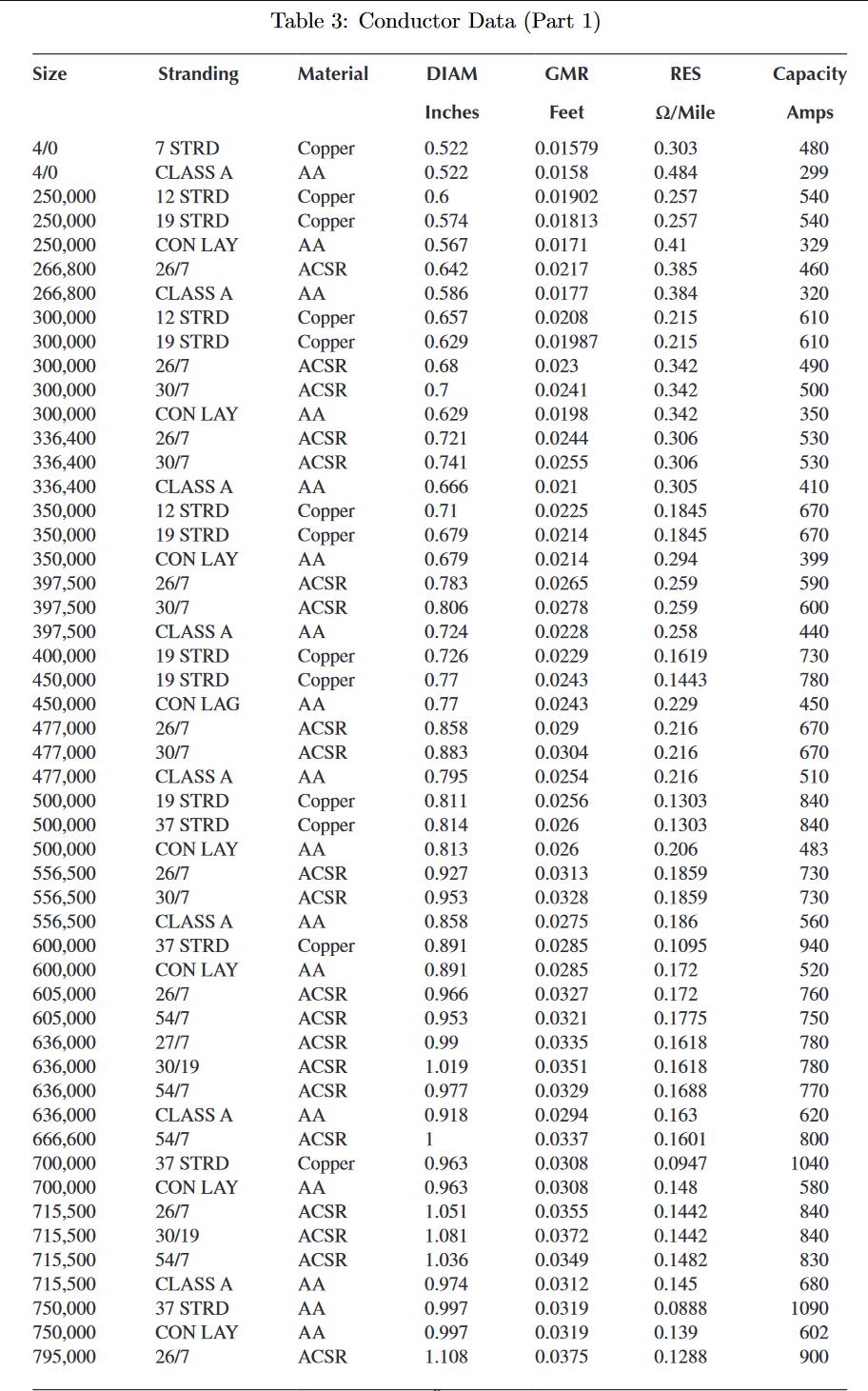
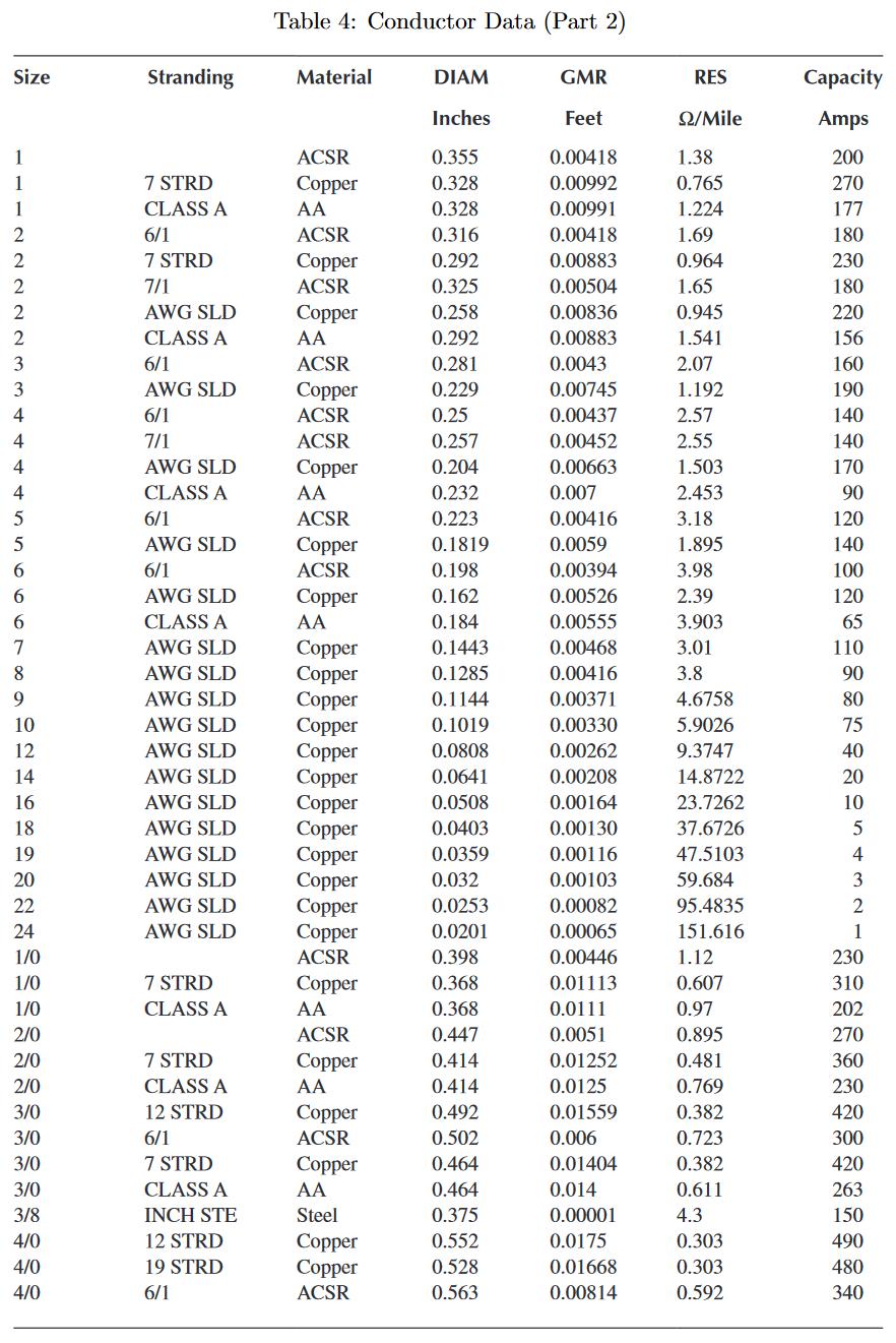
Consider a three-phase four-wire grounded distribution overhead line where the coordinates of the three phases and the neutral conductor are specified as below (the units are all in [ft]): Phase a: (xa, ya) - (0,25) Phase b: (xb, yb)=(3, 27) Phase c: (xc, yc) = (6.5, 24) Neutral conductor: (xn, yn) = (3.5, 20) The phase conductors are NOT transposed and the conductor types are provided below (please find the conductor data in Tables 3 and 4): Phase conductors: 336, 400 30/7 ACSR Neutral conductor: 4/0 6/1 ACSR (a) Determine the phase impedance matrix, [Zabc], in [ 2/mile ]. (b) Determine the phase admittance matrix, [Yabc], in [uS /mile ]. (c) Determine the generalized matrices (two-port model matrices) for this line if the line length is 3, 000 [ft]. (d) The line is serving a balanced three-phase load of 8, 000 [kVA], with balanced voltages of 12.47 [kv] line to line and a power factor of 0.9 lagging. Compute the line- to-neutral voltages at the source end of the line. (e)Suppose that the above line maintains the same arrangement for the first half (the first 1500 [ft]), however, for the second half the position of phases a and c are switched. Compute the generalized matrices (two-port model matrices) for the whole line of 3000 [ft]. Size 4/0 4/0 250,000 250,000 250,000 266,800 266,800 300,000 300,000 300,000 300,000 300,000 336,400 336,400 336,400 350,000 350,000 350,000 397,500 397,500 397,500 400,000 450,000 450,000 477,000 477,000 477,000 500,000 500,000 500,000 556,500 556,500 556,500 600,000 600,000 605,000 605,000 636,000 636,000 636,000 636,000 666,600 700,000 700,000 715,500 715,500 715,500 715,500 750,000 750,000 795,000 Stranding 7 STRD CLASS A 12 STRD 19 STRD CON LAY 26/7 CLASS A 12 STRD 19 STRD 26/7 30/7 CON LAY 26/7 30/7 CLASS A 12 STRD 19 STRD CON LAY 26/7 30/7 CLASS A 19 STRD 19 STRD CON LAG 26/7 30/7 CLASS A 19 STRD 37 STRD CON LAY 26/7 30/7 CLASS A 37 STRD CON LAY 26/7 54/7 27/7 30/19 54/7 CLASS A 54/7 37 STRD CON LAY 26/7 30/19 54/7 CLASS A 37 STRD CON LAY 26/7 Table 3: Conductor Data (Part 1) Material Copper AA Copper Copper AA ACSR AA Copper Copper ACSR ACSR AA ACSR ACSR AA Copper Copper AA ACSR ACSR AA Copper Copper AA ACSR ACSR AA Copper Copper AA ACSR ACSR AA Copper AA ACSR ACSR ACSR ACSR ACSR AA ACSR Copper AA ACSR ACSR ACSR AA AA AA ACSR DIAM Inches 0.522 0.522 0.6 0.574 0.567 0.642 0.586 0.657 0.629 0.68 0.7 0.629 0.721 0.741 0.666 0.71 0.679 0.679 0.783 0.806 0.724 0.726 0.77 0.77 0.858 0.883 0.795 0.811 0.814 0.813 0.927 0.953 0.858 0.891 0.891 0.966 0.953 0.99 1.019 0.977 0.918 1 0.963 0.963 1.051 1.081 1.036 0.974 0.997 0.997 1.108 GMR Feet 0.01579 0.0158 0.01902 0.01813 0.0171 0.0217 0.0177 0.0208 0.01987 0.023 0.0241 0.0198 0.0244 0.0255 0.021 0.0225 0.0214 0.0214 0.0265 0.0278 0.0228 0.0229 0.0243 0.0243 0.029 0.0304 0.0254 0.0256 0.026 0.026 0.0313 0.0328 0.0275 0.0285 0.0285 0.0327 0.0321 0.0335 0.0351 0.0329 0.0294 0.0337 0.0308 0.0308 0.0355 0.0372 0.0349 0.0312 0.0319 0.0319 0.0375 RES /Mile 0.303 0.484 0.257 0.257 0.41 0.385 0.384 0.215 0.215 0.342 0.342 0.342 0.306 0.306 0.305 0.1845 0.1845 0.294 0.259 0.259 0.258 0.1619 0.1443 0.229 0.216 0.216 0.216 0.1303 0.1303 0.206 0.1859 0.1859 0.186 0.1095 0.172 0.172 0.1775 0.1618 0.1618 0.1688 0.163 0.1601 0.0947 0.148 0.1442 0.1442 0.1482 0.145 0.0888 0.139 0.1288 Capacity Amps 480 299 540 540 329 460 320 610 610 490 500 350 530 530 410 670 670 399 590 600 440 730 780 450 670 670 510 840 840 483 730 730 560 940 520 760 750 780 780 770 620 800 1040 580 840 840 830 680 1090 602 900 Size 1 2 2 3 3 4 4 4 4 5 5 6 6 6 7 8 9 10 12 14 16 18 19 20 22 24 1/0 1/0 1/0 2/0 2/0 2/0 3/0 3/0 3/0 3/0 3/8 4/0 4/0 4/0 Stranding 7 STRD CLASS A 6/1 7 STRD 7/1 AWG SLD CLASS A 6/1 AWG SLD 6/1 7/1 AWG SLD CLASS A 6/1 AWG SLD 6/1 AWG SLD CLASS A AWG SLD AWG SLD AWG SLD AWG SLD AWG SLD AWG SLD AWG SLD AWG SLD AWG SLD AWG SLD AWG SLD AWG SLD 7 STRD CLASS A 7 STRD CLASS A 12 STRD 6/1 7 STRD CLASS A INCH STE 12 STRD 19 STRD 6/1 Table 4: Conductor Data (Part 2) Material ACSR Copper AA ACSR Copper ACSR Copper AA ACSR Copper ACSR ACSR Copper AA ACSR Copper ACSR Copper AA Copper Copper Copper Copper Copper Copper Copper Copper Copper Copper Copper Copper ACSR Copper AA ACSR Copper AA Copper ACSR Copper AA Steel Copper Copper ACSR DIAM Inches 0.355 0.328 0.328 0.316 0.292 0.325 0.258 0.292 0.281 0.229 0.25 0.257 0.204 0.232 0.223 0.1819 0.198 0.162 0.184 0.1443 0.1285 0.1144 0.1019 0.0808 0.0641 0.0508 0.0403 0.0359 0.032 0.0253 0.0201 0.398 0.368 0.368 0.447 0.414 0.414 0.492 0.502 0.464 0.464 0.375 0.552 0.528 0.563 GMR Feet 0.00418 0.00992 0.00991 0.00418 0.00883 0.00504 0.00836 0.00883 0.0043 0.00745 0.00437 0.00452 0.00663 0.007 0.00416 0.0059 0.00394 0.00526 0.00555 0.00468 0.00416 0.00371 0.00330 0.00262 0.00208 0.00164 0.00130 0.00116 0.00103 0.00082 0.00065 0.00446 0.01113 0.0111 0.0051 0.01252 0.0125 0.01559 0.006 0.01404 0.014 0.00001 0.0175 0.01668 0.00814 RES Q2/Mile 1.38 0.765 1.224 1.69 0.964 1.65 0.945 1.541 2.07 1.192 2.57 2.55 1.503 2.453 3.18 1.895 3.98 2.39 3.903 3.01 3.8 4.6758 5.9026 9.3747 14.8722 23.7262 37.6726 47.5103 59.684 95.4835 151.616 1.12 0.607 0.97 0.895 0.481 0.769 0.382 0.723 0.382 0.611 4.3 0.303 0.303 0.592 Capacity Amps 200 270 177 180 230 180 220 156 160 190 140 140 170 90 120 140 100 120 65 110 90 80 75 40 20 10 5 4 3 2 1 230 310 202 270 360 230 420 300 420 263 150 490 480 340
Step by Step Solution
3.44 Rating (154 Votes )
There are 3 Steps involved in it
To solve this problem well need to use the provided conductor data to calculate the phase impedance and admittance matrices Well also calculate the generalized matrices for a given line length and com... View full answer

Get step-by-step solutions from verified subject matter experts