

Question: Consider an asynchronous sequential circuit to implement a D - register with two inputs, D and CLK and an output Q. The output, Q, follows
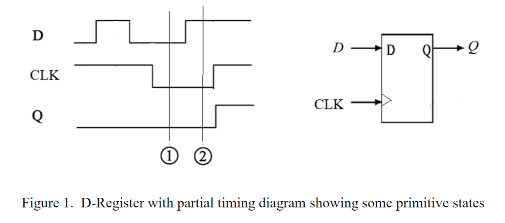
Consider an asynchronous sequential circuit to implement a D - register with two inputs, D and CLK and an output Q. The output, Q, follows D when the CLK transitions from low to high (0 to 1) i.e. edge triggered. See figure 1.
1) Complete the timing diagram and show the eight primitive states. Draw the Moore primitive flow table. 2) Draw the Moore implication table and define the possible mergable states. 3) Draw the merged flow table(s). 4) Assign state variable(s) and complete a Moore design using AND, OR and NOT gates.
CLK CLK Figure 1. D-Register with partial timing diagram showing some primitive states CLK CLK Figure 1. D-Register with partial timing diagram showing some primitive states
Step by Step Solution
There are 3 Steps involved in it

Get step-by-step solutions from verified subject matter experts