

Question: Consider the 7 4 HC 1 9 5 4 - bit parallel shift register ( see the example on pp . 4 4 6 -
Consider the HC bit parallel shift register see the example on pp in the textbook
a Determine the waveforms for the Q outputs given the signals below. At each clock cycle, indicate the mode of operation of the shift register eg LD Set, Reset, CLR
Note: You can printout the worksheet on the last page to answer this question. If you choose not to use the worksheet, be sure to redraw all the relevant waveforms so your answer is clear.
b Use two HCbit shift registers to create an bit shift register. Show all the required connections between the relevant pins on the two ICs.
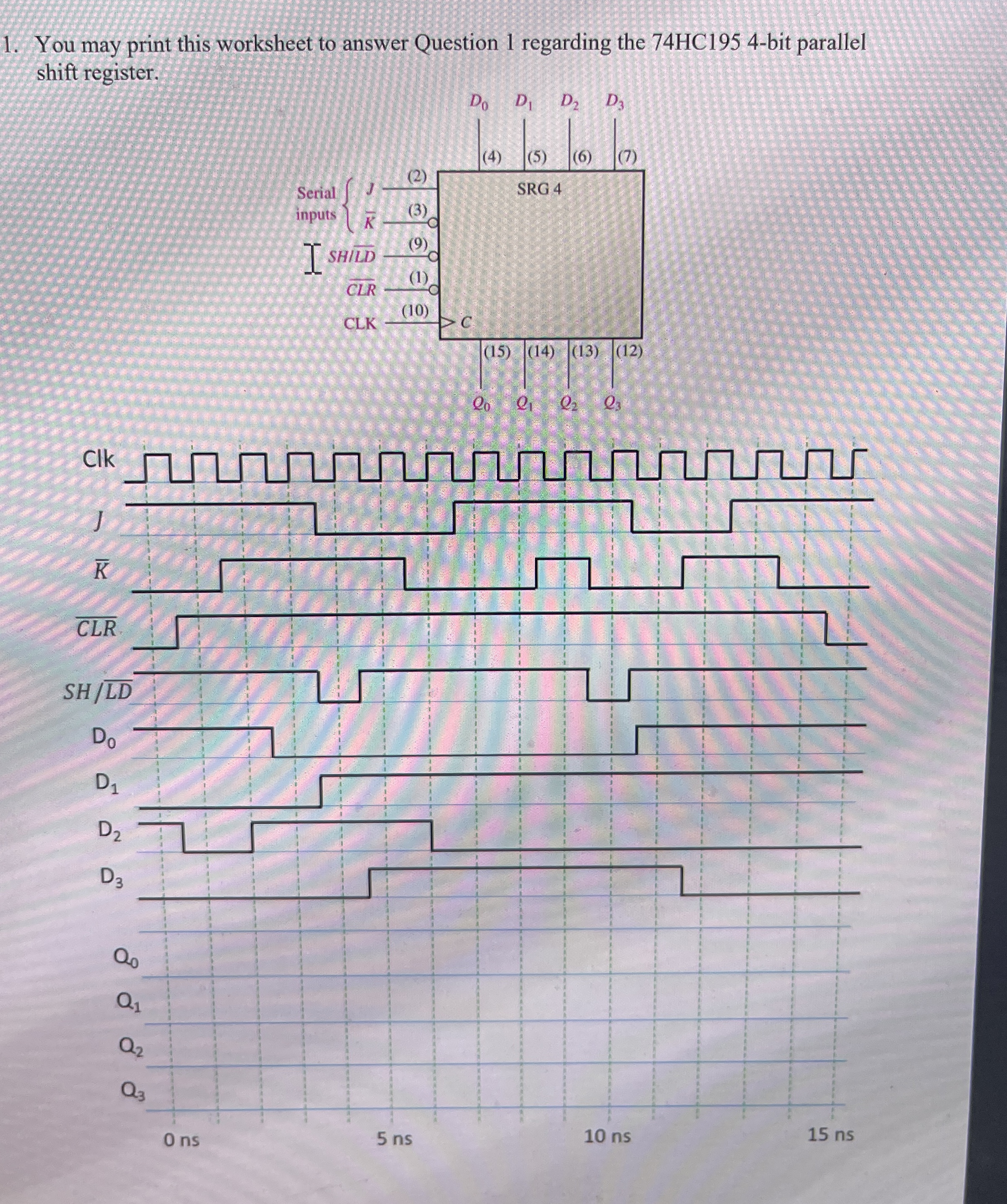
You may print this worksheet to answer Question regarding the HC bit parallel shift register.
Step by Step Solution
There are 3 Steps involved in it
1 Expert Approved Answer
Step: 1 Unlock

Question Has Been Solved by an Expert!
Get step-by-step solutions from verified subject matter experts
Step: 2 Unlock
Step: 3 Unlock