

Question: Consider the beam shown in ( Figure 1 ) . Take P = 1 kip and w = 1 . 9 k i p f
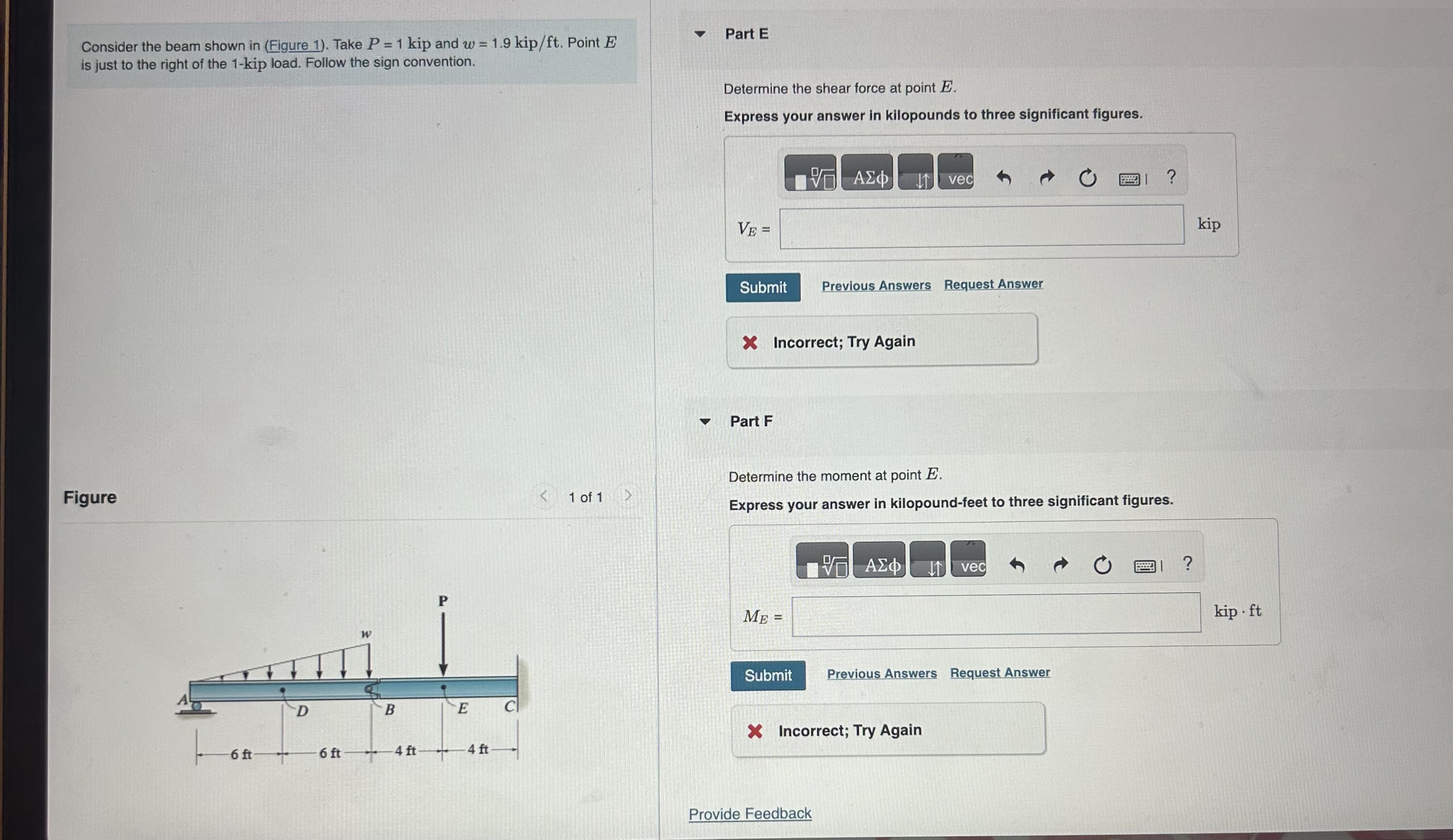
Consider the beam shown in Figure Take kip and Point is just to the right of the kip load. Follow the sign convention.
Part A
Determine the normal force at point
Express your answer in kilopounds to three significant figures.
Previous Answers
Part B
Determine the shear force at point
Express your answer in kilopounds to three significant figures.
Figure
of
Previous Answers
Request Answer
Part C
Determine the moment at point
Express your answer in kilopoundfeet to three significant figures.Consider the beam shown in Figure Take kip and Point is just to the right of the kip load. Follow the sign convention.
Part C
Determine the moment at point
Express your answer in kilopoundfeet to three significant figures.
kip ft
Request Answer
X Incorrect; Try Again
Part D
Determine the normal force at point
Express your answer in kilopounds to three significant figures.
Figure
of
Subnit
Previous Answers
Part E
Determine the shear force at point
Express your answer in kilopounds to three significant figures.Consider the beam shown in Figure Take kip and Point is just to the right of the kip load. Follow the sign convention.
Part E
Determine the shear force at point
Express your answer in kilopounds to three significant figures.
kip
Previous Answers
Request Answer
Part F
Determine the moment at point
Express your answer in kilopoundfeet to three significant figures.
kip
Previous Answers
Request Answer
Incorrect; Try Again
Provide Feedback
Step by Step Solution
There are 3 Steps involved in it
1 Expert Approved Answer
Step: 1 Unlock

Question Has Been Solved by an Expert!
Get step-by-step solutions from verified subject matter experts
Step: 2 Unlock
Step: 3 Unlock