

Question: Consider the circuit in Figure 1. It is a 4-bit synchronous counter which uses four T-type flip-flops. The counter increments its value on each positive
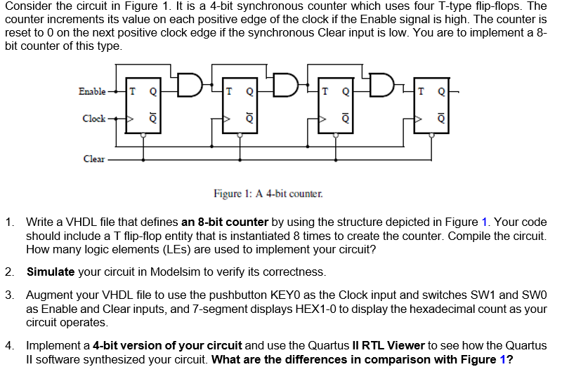
Consider the circuit in Figure 1. It is a 4-bit synchronous counter which uses four T-type flip-flops. The counter increments its value on each positive edge of the clock if the Enable signal is high. The counter is reset to 0 on the next positive clock edge if the synchronous Clear input is low. You are to implement a 8- bit counter of this type. Enable IT O Clock Clear Figure 1: A 4-bit counter 1. Write a VHDL file that defines an 8-bit counter by using the structure depicted in Figure 1. Your code should include a T flip-flop entity that is instantiated 8 times to create the counter. Compile the circuit. How many logic elements (LES) are used to implement your circuit? 2. Simulate your circuit in Modelsim to verify its correctness. 3. Augment your VHDL file to use the pushbutton KEYO as the clock input and switches SW1 and SWO as Enable and Clear inputs, and 7-segment displays HEX1-0 to display the hexadecimal count as your circuit operates. 4. Implement a 4-bit version of your circuit and use the Quartus II RTL Viewer to see how the Quartus Il software synthesized your circuit. What are the differences in comparison with Figure 1
Step by Step Solution
There are 3 Steps involved in it

Get step-by-step solutions from verified subject matter experts