

Question: Consider the circuit shown in the figure below, with two inputs to pins X1 and Y1 respectively and some other connections to an AD633
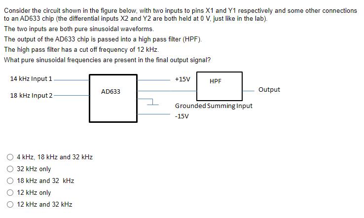
Consider the circuit shown in the figure below, with two inputs to pins X1 and Y1 respectively and some other connections to an AD633 chip (the differential inputs X2 and Y2 are both held at 0 V, just like in the lab). The two inputs are both pure sinusoidal waveforms. The output of the AD633 chip is passed into a high pass filter (HPF). The high pass filter has a cut off frequency of 12 kHz. What pure sinusoidal frequencies are present in the final output signal? 14 kHz Input 1. 18 kHz Input 2 4 kHz, 18 kHz and 32 kHz 32 kHz only 18 kHz and 32 kHz 12 kHz only 12 kHz and 32 kHz AD633 +15V HPF Grounded Summing Input -15V Output
Step by Step Solution
There are 3 Steps involved in it
Introduction The given circuit involves an AD633 chip differential inputs X1 Y1 X2 Y2 and a high pas... View full answer

Get step-by-step solutions from verified subject matter experts