

Question: Consider the crane tower structure shown in Figure 3 . A single point load P ( k N ) is applied at node I as
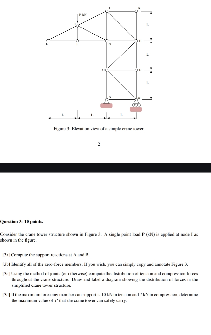
Consider the crane tower structure shown in Figure A single point load is applied at node I as shown in the figure.
a Compute the support reactions at A and B
b Identify all of the zeroforce members. If you wish, you can simply copy and annotate Figure
c Using the method of joints or otherwise compute the distribution of tension and compression forces throughout the crane structure. Draw and label a diagram showing the distribution of forces in the simplified crane tower structure.
d If the maximum force any member can support is kN in tension and kN in compression, determine the maximum value of that the crane tower can safely carry.
Question : points.
Consider the crane tower structure shown in Figure A single point load is applied at node I as shown in the figure.
a Compute the support reactions at A and B
b Identify all of the zeroforce members. If you wish, you can simply copy and annotate Figure
c Using the method of joints or otherwise compute the distribution of tension and compression forces throughout the crane structure. Draw and label a diagram showing the distribution of forces in the simplified crane tower structure.
d If the maximum force any member can support is kN in tension and kN in compression, determine the maximum value of that the crane tower can safely carry.
Step by Step Solution
There are 3 Steps involved in it
1 Expert Approved Answer
Step: 1 Unlock

Question Has Been Solved by an Expert!
Get step-by-step solutions from verified subject matter experts
Step: 2 Unlock
Step: 3 Unlock