

Question: Consider the datapath in Figure 1 and the program code in Listning 1 on the last page. Assume that the ALU corresponds to the one
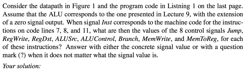
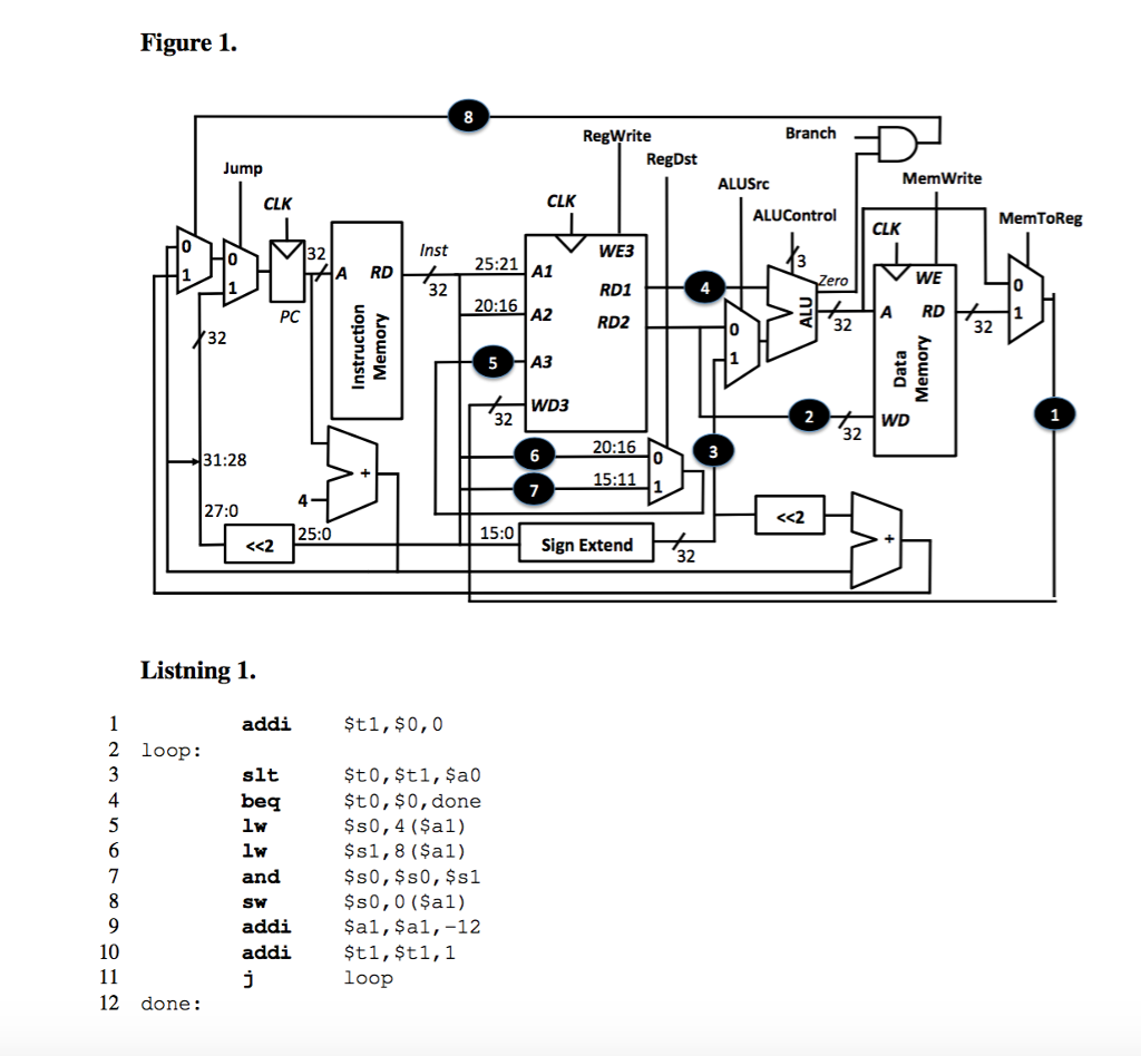
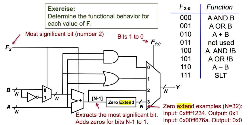
Consider the datapath in Figure 1 and the program code in Listning 1 on the last page. Assume that the ALU corresponds to the one presented in Lecture 9, with the extension of a zero signal output. When signal Inst corresponds to the machine code for the instruc- tions on code lines 7, 8, and 11, what are then the values of the 8 control signals Jump, Reg Write, RegDst, ALUSrc, ALUControl, Branch, MemWrite, and MemToReg, for each of these instructions? Answer with either the concrete signal value or with a question mark (?) when it does not matter what the signal value is. Your solution: Consider the datapath in Figure 1 and the program code in Listning 1 on the last page. Assume that the ALU corresponds to the one presented in Lecture 9, with the extension of a zero signal output. When signal Inst corresponds to the machine code for the instruc- tions on code lines 7, 8, and 11, what are then the values of the 8 control signals Jump, Reg Write, RegDst, ALUSrc, ALUControl, Branch, MemWrite, and MemToReg, for each of these instructions? Answer with either the concrete signal value or with a question mark (?) when it does not matter what the signal value is. Your solution
Step by Step Solution
There are 3 Steps involved in it

Get step-by-step solutions from verified subject matter experts