

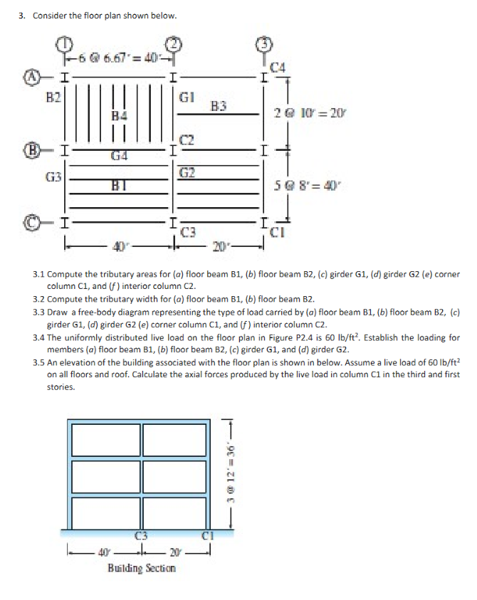
Question: Consider the floor plan shown below. 3 . 1 Compute the tributary areas for ( a ) floor beam B 1 , ( b )
Consider the floor plan shown below.
Compute the tributary areas for floor beam Bb floor beam Bc girder G girder Ge corner column and interior column
Compute the tributary width for a floor beam Bb floor beam B
Draw a freebody diagram representing the type of load carried by floor beam floor beam girder G girder Ge corner column C and interior column C
The uniformly distributed live load on the floor plan in Figure P is Establish the loading for members floor beam B floor beam girder and girder G
An elevation of the building associated with the floor plan is shown in below. Assume a live load of on all floors and roof. Calculate the axial forces produced by the live load in column in the third and first stories.
Step by Step Solution
There are 3 Steps involved in it
1 Expert Approved Answer
Step: 1 Unlock

Question Has Been Solved by an Expert!
Get step-by-step solutions from verified subject matter experts
Step: 2 Unlock
Step: 3 Unlock