

Question: Consider the floor system shown in Figure 1 , which consists of a slab supported on a number of parallel beams with cantilever extensions. The
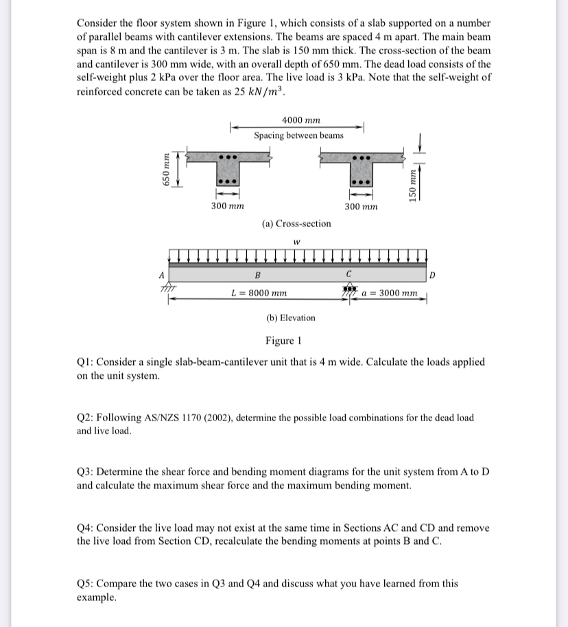
Consider the floor system shown in Figure which consists of a slab supported on a number of parallel beams with cantilever extensions. The beams are spaced apart. The main beam span is and the cantilever is The slab is thick. The crosssection of the beam and cantilever is wide, with an overall depth of The dead load consists of the selfweight plus kPa over the floor area. The live load is kPa. Note that the selfweight of reinforced concrete can be taken as
rigure
Q: Consider a single slabbeamcantilever unit that is wide. Calculate the loads applied on the unit system.
Q: Following ASNZS determine the possible load combinations for the dead load and live load.
Q: Determine the shear force and bending moment diagrams for the unit system from to and calculate the maximum shear force and the maximum bending moment.
Q: Consider the live load may not exist at the same time in Sections and and remove the live load from Section recalculate the bending moments at points and
Q: Compare the two cases in Q and Q and discuss what you have learned from this example.
Step by Step Solution
There are 3 Steps involved in it
1 Expert Approved Answer
Step: 1 Unlock

Question Has Been Solved by an Expert!
Get step-by-step solutions from verified subject matter experts
Step: 2 Unlock
Step: 3 Unlock