

Question: Consider the following MIPS code: 11: DADD R1, R5, R3 12: BNEZ R1, L1 13: DADD R3, R2, R5 14: DSUB R5, R2, R5 15:
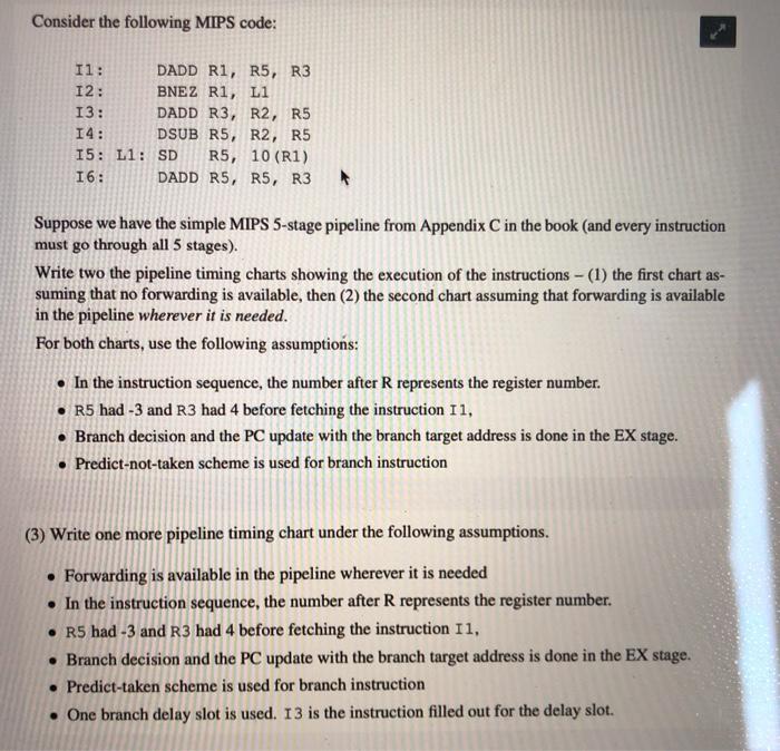
Consider the following MIPS code: 11: DADD R1, R5, R3 12: BNEZ R1, L1 13: DADD R3, R2, R5 14: DSUB R5, R2, R5 15: L1: SD R5, 10 (R1) 16: DADD R5, R5, R3 Suppose we have the simple MIPS 5-stage pipeline from Appendix C in the book (and every instruction must go through all 5 stages). Write two the pipeline timing charts showing the execution of the instructions - (1) the first chart as- suming that no forwarding is available, then (2) the second chart assuming that forwarding is available in the pipeline wherever it is needed. For both charts, use the following assumptions: In the instruction sequence, the number after R represents the register number. R5 had -3 and R3 had 4 before fetching the instruction 11, Branch decision and the PC update with the branch target address is done in the EX stage. Predict-not-taken scheme is used for branch instruction (3) Write one more pipeline timing chart under the following assumptions. Forwarding is available in the pipeline wherever it is needed In the instruction sequence, the number after R represents the register number. R5 had -3 and R3 had 4 before fetching the instruction 11, Branch decision and the PC update with the branch target address is done in the EX stage. Predict-taken scheme is used for branch instruction One branch delay slot is used. 13 is the instruction filled out for the delay slot. Consider the following MIPS code: 11: DADD R1, R5, R3 12: BNEZ R1, L1 13: DADD R3, R2, R5 14: DSUB R5, R2, R5 15: L1: SD R5, 10 (R1) 16: DADD R5, R5, R3 Suppose we have the simple MIPS 5-stage pipeline from Appendix C in the book (and every instruction must go through all 5 stages). Write two the pipeline timing charts showing the execution of the instructions - (1) the first chart as- suming that no forwarding is available, then (2) the second chart assuming that forwarding is available in the pipeline wherever it is needed. For both charts, use the following assumptions: In the instruction sequence, the number after R represents the register number. R5 had -3 and R3 had 4 before fetching the instruction 11, Branch decision and the PC update with the branch target address is done in the EX stage. Predict-not-taken scheme is used for branch instruction (3) Write one more pipeline timing chart under the following assumptions. Forwarding is available in the pipeline wherever it is needed In the instruction sequence, the number after R represents the register number. R5 had -3 and R3 had 4 before fetching the instruction 11, Branch decision and the PC update with the branch target address is done in the EX stage. Predict-taken scheme is used for branch instruction One branch delay slot is used. 13 is the instruction filled out for the delay slot
Step by Step Solution
There are 3 Steps involved in it

Get step-by-step solutions from verified subject matter experts