

Question: Consider the rotor with the gear train driving a robot arm through a flexible shaft, as shown in Fig. 1. An external motor (not shown)
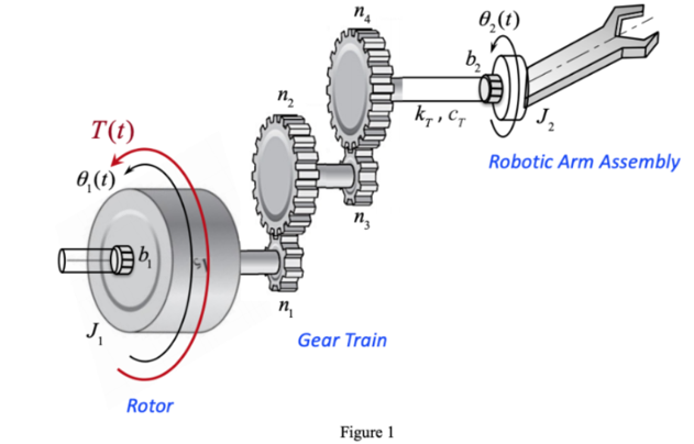
Consider the rotor with the gear train driving a robot arm through a flexible shaft, as shown in Fig. 1. An external motor (not shown) delivers the input torque T(t) to the Rotor with inertia J 1 . The Rotor is connected to the gear wheel n 1 of the gear train with a very short and very stiff shaft. Gear n2 is larger than gear n 1 , and their gear ratio is n 2 /n 1 = N 1 ; similarly, gear n 4 is larger than gear n 3 , and their gear ratio is: n 4 /n 3 = N 2 . Inertia of gears n 1 , n 2 , n 3 , and n 4 can be neglected. The rotor is supported by bearings with damping coefficient b 1 . Gear Train and Robotic Arm Assembly are connected by a flexible shaft. The elastic property of this shaft is represented by a parallel connection of a torsional spring with stiffness coefficient of k T and torsional damper with damping coefficient of c T . The Robotic Arm Assembly has inertia J 2 , and is supported by bearings that contain some hydraulic fluid with viscous friction coefficient b 2 .
a) Derive the governing equations for this system
b) Derive the transfer function ?(s)/T(s), where ?(s) and T(s) are the Laplace transforms of the rotation speed of the Robotic Arm Assembly ?(t) = , and of the applied torque T(t) respectively.
c) Obtain a state representation for the dynamic system, with T(t) as an input, and ?(t) as an output.
T(t) 8,(1) J Rotor n Gear Train Figure 1 0 (1) b k, CT Robotic Arm Assembly
Step by Step Solution
3.44 Rating (160 Votes )
There are 3 Steps involved in it
To solve this problem well address each part step by step a Derive the Governing Equations 1 Rotor Dynamics J J1 ddottheta1t Tt b1 dottheta1t tautextg... View full answer

Get step-by-step solutions from verified subject matter experts