

Question: A position control system is shown in Fig. D9.2(a). The angular position (boldsymbol{r}) is the reference input to the system. The output shaft position determines
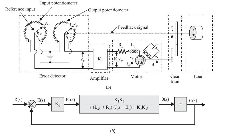
A position control system is shown in Fig. D9.2(a). The angular position \(\boldsymbol{r}\) is the reference input to the system. The output shaft position determines the angular position \(\boldsymbol{c}\) of wiper arm of the output potentiometer. The error voltage \(e_{v}=e_{r}-e_{c}\) where \(e_{r}=\mathrm{K}_{0} . r\) and \(e_{c}=\mathrm{K}_{0} . c\) where \(\mathrm{K}_{0}\) is proportionality constant. \(\mathrm{K}_{1}\) is amplifier gain. The amplified output drives armature circuit of the DC motor. A fixed voltage is applied to field winding. The torque developed by motor is
\[
\begin{aligned}
& \mathrm{T}=\mathrm{K}_{2} i_{a} ; \mathrm{K}_{2}=\text { motor torque constant and } \\
& i_{a}=\text { armature current }
\end{aligned}
\]
\(\mathbf{K}_{3}\) is back emf constant. Gear ratio \(\boldsymbol{n}\) of gear train, is so chosen that \(\boldsymbol{c}=\boldsymbol{n} \boldsymbol{\theta}\). The overall system is designed to reduce error \(\boldsymbol{e}=\boldsymbol{r} \boldsymbol{\boldsymbol { c }}\) to zero if it exists. \(\mathrm{J}_{0}\) is the inertia of the motor plus load plus gear train referred to motor shaft. \(\mathrm{B}_{0}\) is viscous friction coefficient of motor plus load plus gear train referred to motor shaft. Show that system of Fig. D9.2(a) and block diagram shown in Fig. D9.2(b) are equivalent.
\[
\mathrm{L}_{a} \frac{d i_{a}}{d t}+\mathrm{R}_{a} i_{a}+\mathrm{K}_{3} \frac{d \theta}{d t}=\mathrm{K}_{1} e_{v}
\]
\[
\begin{aligned}
\mathrm{J}_{0} \frac{d^{2} \theta}{d t^{2}}+\mathrm{B}_{0} \frac{d \theta}{d t} & =\mathrm{T}=\mathrm{K}_{2} i_{a} \\
c & =n \theta
\end{aligned}
\]
Reference input R(s) Input potentiometer Error detector E(s) E,(s) -Output potentiometer K Amplifier (a) Feedback signal (b) Ra La MW-0000) leeee Motor K K s (Ls+R) (Jos+B) + KK3s 0(s) Gear train n Load C(s)
Step by Step Solution
3.30 Rating (150 Votes )
There are 3 Steps involved in it
The challenge here is to establish the equivalence between the physical control system in Fig D92a and its block diagram representation in Fig D92b To do this we need to translate the physical compone... View full answer

Get step-by-step solutions from verified subject matter experts