

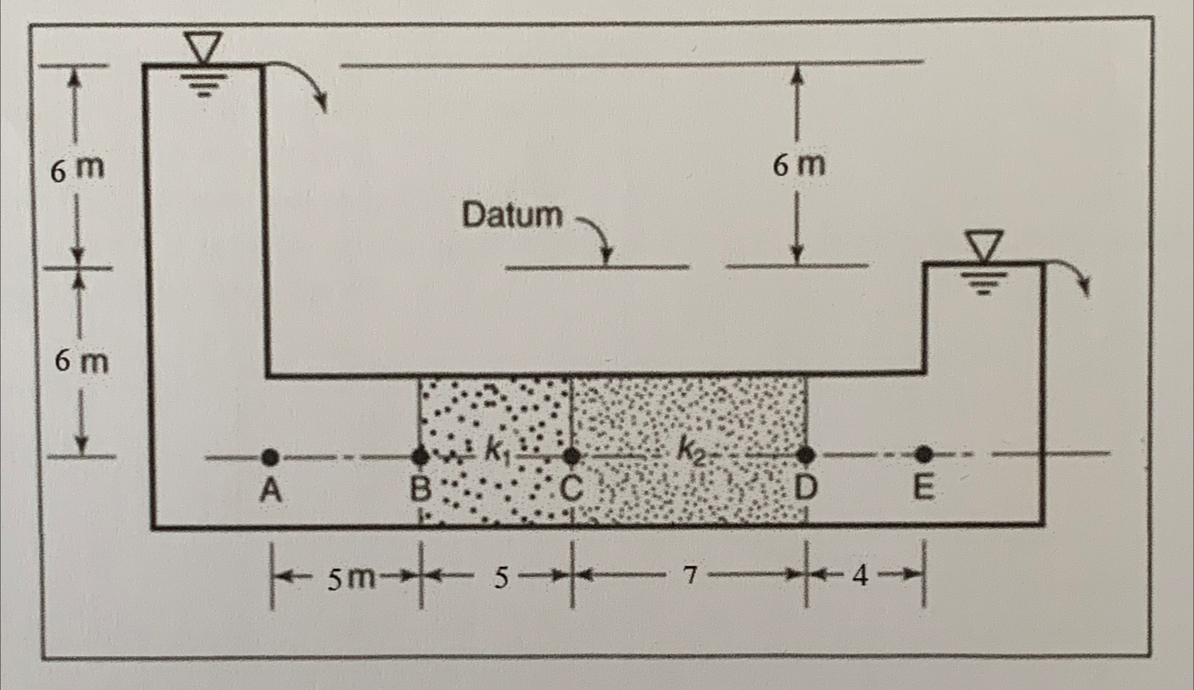
Question: Consider the setup shown in the Figure below in which two different soil layers are located inside a cylindrical tube of 2 0 0 m
Consider the setup shown in the Figure below in which two different soil layers are located inside a cylindrical tube of A constant head difference is maintained across the soil sample. The porosities and hydraulic conductivities of the two soils in the direction of the flow are as follows: ;
a Determine the quantity of water flowing through the sample per hour.
b Determine the elevation head Z pressure head hp and the total head h at points A B C D &E
c Plot the variation of the elevation head, pressure head and the total head with the horizontal distance along the sample axis.
d Plot the variations of discharge velocity and the seepage velocity along the sample axis.
Step by Step Solution
There are 3 Steps involved in it
1 Expert Approved Answer
Step: 1 Unlock

Question Has Been Solved by an Expert!
Get step-by-step solutions from verified subject matter experts
Step: 2 Unlock
Step: 3 Unlock