

Question: Construct the diode rectification circuit shown in Figure 3 , with the capacitor disconnected. Use signal generator as a . c . source to provide
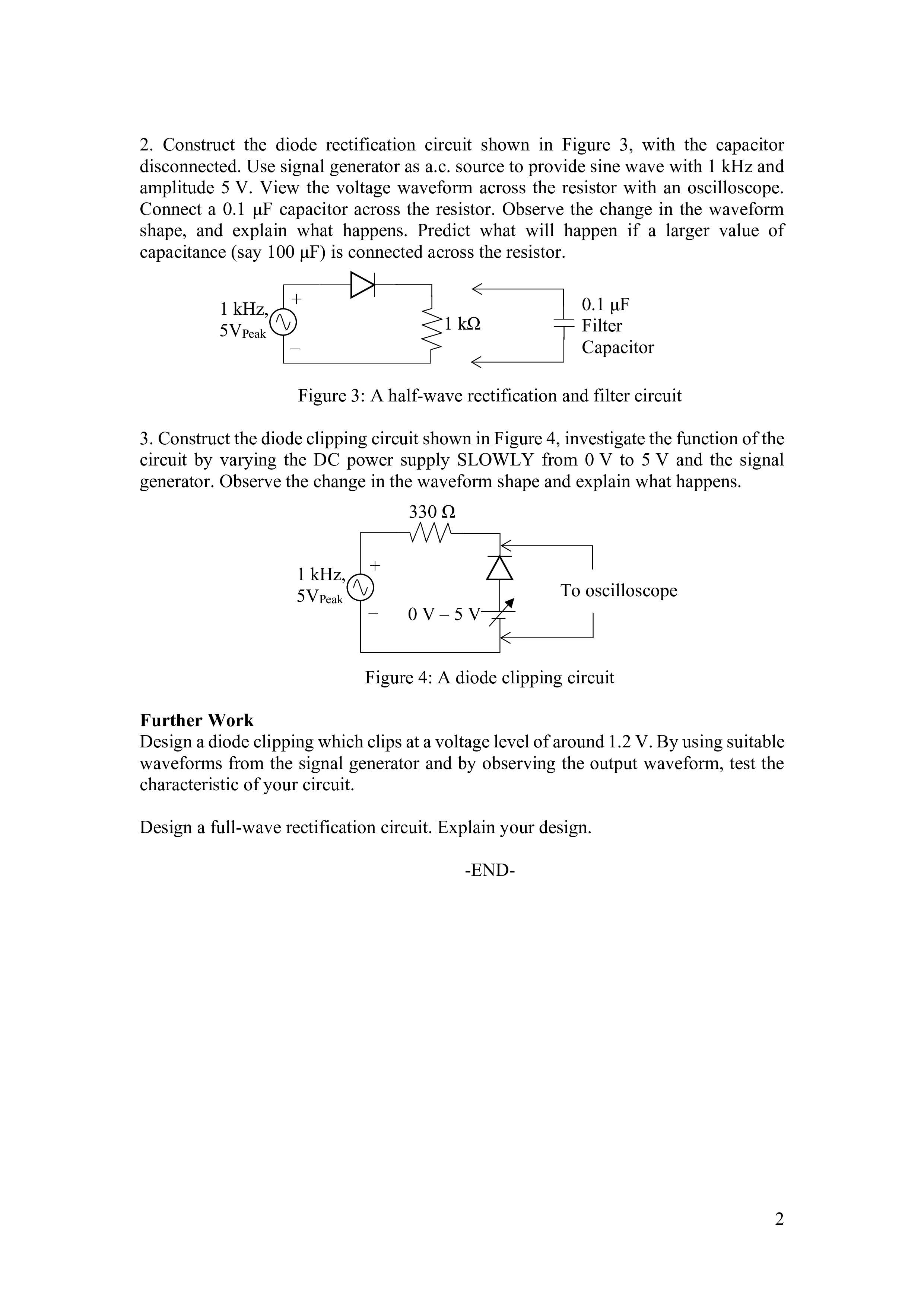
Construct the diode rectification circuit shown in Figure with the capacitor
disconnected. Use signal generator as ac source to provide sine wave with kHz and
amplitude V View the voltage waveform across the resistor with an oscilloscope.
Connect a muF capacitor across the resistor. Observe the change in the waveform
shape, and explain what happens. Predict what will happen if a larger value of
capacitance say muF is connected across the resistor.
Figure : A halfwave rectification and filter circuit
Construct the diode clipping circuit shown in Figure investigate the function of the
circuit by varying the DC power supply SLOWLY from V to V and the signal
generator. Observe the change in the waveform shape and explain what happens.
Figure : A diode clipping circuit
Further Work
Design a diode clipping which clips at a voltage level of around V By using suitable
waveforms from the signal generator and by observing the output waveform, test the
characteristic of your circuit.
Design a fullwave rectification circuit. Explain the design briefly.
Step by Step Solution
There are 3 Steps involved in it
1 Expert Approved Answer
Step: 1 Unlock

Question Has Been Solved by an Expert!
Get step-by-step solutions from verified subject matter experts
Step: 2 Unlock
Step: 3 Unlock