

Question: Continuing in the problem-solving cycle, the team proceeds with Step 5. Plan: Problem Process, Document and Analyze the team visited the customer's assembly plant to
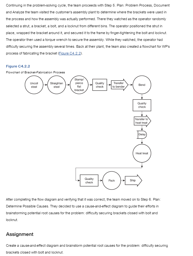
Continuing in the problem-solving cycle, the team proceeds with Step 5. Plan: Problem Process, Document and Analyze the team visited the customer's assembly plant to determine where the brackets were used in the process and how the assembly was actually performed. There they watched as the operator randomly selected a strut, a bracket, a bolt, and a locknut from different bins. The operator positioned the strut in place, wrapped the bracket around it, and secured it to the frame by finger-tightening the bolt and locknut. The operator then used a torque wrench to secure the assembly. While they watched, the operator had difficulty securing the assembly several times. Back at their plant, the team also created a flowchart for WP's process of fabricating the bracket (Figure C4.2.2). Figu-- n Flow After completing the flow diagram and verifying that it was correct, the team moved on to Step 6 . Plan: Determine Possible Causes. They decided to use a cause-and-effect diagram to guide their efforts in brainstorming potential root causes for the problem: difficulty securing brackets closed with bolt and locknut. Assignment Create a cause-and-effect diagram and brainstorm potential root causes for the problem: difficulty securing brackets closed with bolt and locknut. Through the use of a cause-and-effect diagram, the engineers determine that the most likely cause of the problems experienced by the customer is the alignment of the holes. At some stage in the formation process, the holes end up off center. Combining this information with the WHYWHY diagram conclusion that hole alignment was critical for smooth installation during assembly narrows the search for a root cause. Unfortunately, the team still doesn't know why the holes are not properly aligned. They decide to create another cause-and-effect diagram that focuses on causes of improper hole alignment. Assignment Create a second cause-and-effect diagram that focuses on the root causes of improper hole alignment. At this point in the problem-solving process, it would be appropriate to use statistical information to determine whether the holes are truly not properly aligned. The team would confirm their suspicions during the next production run by having the press operator take samples and measure the angle between the centers of the holes for each sample. This data would then be utilized to create a histogram and compare the process performance with the specification for the angle between insert hole A and insert hole B of 0.00 with a tolerance of 0.30. Hole alignment problems are confirmed through the use of histograms in should you choose to use it. Histograms are one of the problem-solving techniques discussed in Step 6
Step by Step Solution
There are 3 Steps involved in it

Get step-by-step solutions from verified subject matter experts