

Question: Convert the following VHDL code into a schematic in the box below. Use two 4:1 multiplexers one 2:1 multiplexer and a single D type flip-flop;
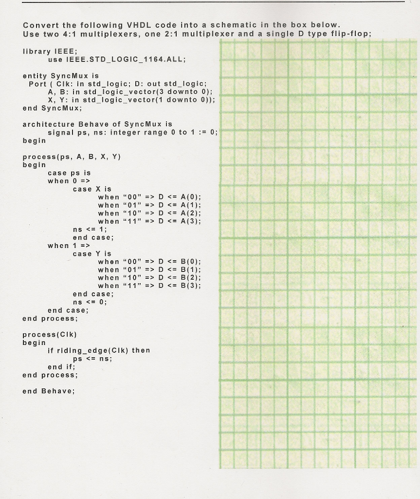
Convert the following VHDL code into a schematic in the box below. Use two 4:1 multiplexers one 2:1 multiplexer and a single D type flip-flop; library IEEE; use IEEE. STD_LOGIC_11 64 .ALL; entity Sync Mux is Port (Clk: in std_logic; D: out std_logic; A, B: in std_logic_vector (3 downto 0); X, Y: in std_logic_vector (1 downto 0)); end Sync Mux; architecture Behave of Sync Mux is signal ps, ns: integer range 0 to 1: = 0; begin process (ps, A, B, X, Y) begin case ps is when 0 => case X is when "00" => D D D D case Y is when "00" => D D D D
Step by Step Solution
There are 3 Steps involved in it
1 Expert Approved Answer
Step: 1 Unlock

Question Has Been Solved by an Expert!
Get step-by-step solutions from verified subject matter experts
Step: 2 Unlock
Step: 3 Unlock