

Question: Create an LTspice schematic file to simulate the circuit shown in Figure 1. The Output voltage (Vout1 and Vout 2) should be 12 V
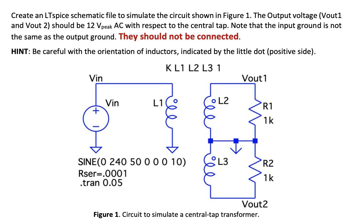
Create an LTspice schematic file to simulate the circuit shown in Figure 1. The Output voltage (Vout1 and Vout 2) should be 12 V peak AC with respect to the central tap. Note that the input ground is not the same as the output ground. They should not be connected. HINT: Be careful with the orientation of inductors, indicated by the little dot (positive side). K L1 L2 L3 1 Vin + Vin L1 SINE (0 240 50 0 0 0 10) Rser=.0001 .tran 0.05 L2 L3 Vout1 R1 1k R2 1k Vout2 Figure 1. Circuit to simulate a central-tap transformer.
Step by Step Solution
There are 3 Steps involved in it
1 Expert Approved Answer
Step: 1 Unlock

Question Has Been Solved by an Expert!
Get step-by-step solutions from verified subject matter experts
Step: 2 Unlock
Step: 3 Unlock