

Question: Lab 1 Measuring Capacitance in Frequency and Time Domains OBJECTIVE e The objective of this lab is to develop two different procedures for measuring capacitance
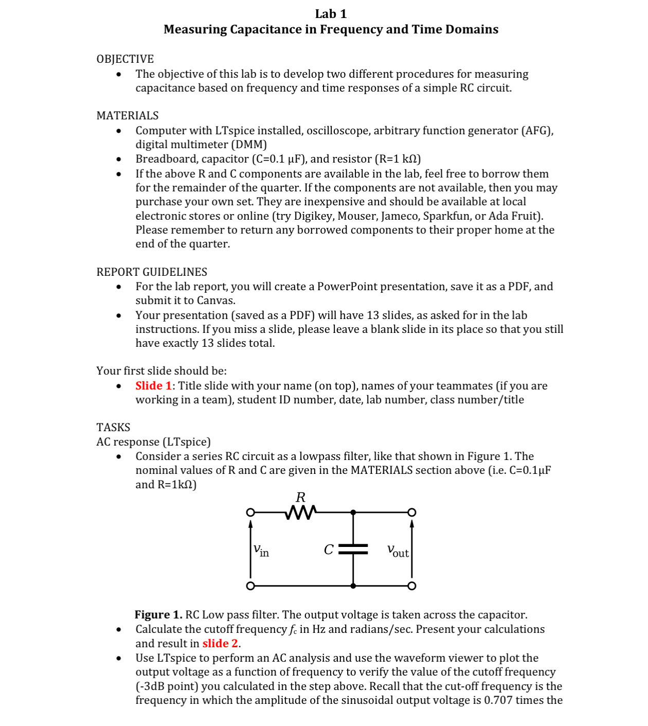
Lab 1 Measuring Capacitance in Frequency and Time Domains OBJECTIVE e The objective of this lab is to develop two different procedures for measuring capacitance based on frequency and time responses of a simple RC circuit. MATERIALS e Computer with LTspice installed, oscilloscope, arbitrary function generator (AFG), digital multimeter (DMM) e Breadboard, capacitor (C=0.1 pF), and resistor (R=1 k(1) e Ifthe above R and C components are available in the lab, feel free to borrow them for the remainder of the quarter. If the components are not available, then you may purchase your own set. They are inexpensive and should be available at local electronic stores or online (try Digikey, Mouser, Jameco, Sparkfun, or Ada Fruit). Please remember to return any borrowed components to their proper home at the end of the quarter. REPORT GUIDELINES e For the lab report, you will create a PowerPoint presentation, save it as a PDF, and submit it to Canvas. e Your presentation (saved as a PDF) will have 13 slides, as asked for in the lab instructions. If you miss a slide, please leave a blank slide in its place so that you still have exactly 13 slides total. Your first slide should be: e Slide 1: Title slide with your name (on top), names of your teammates (if you are working in a team), student ID number, date, lab number, class number/title TASKS AC response (LTspice) + Consider a series RC circuit as a lowpass filter, like that shown in Figure 1. The nominal values of R and C are given in the MATERIALS section above (i.e. C=0.1pF and R=1kQ) R Vin C Vout Figure 1. RC Low pass filter. The output voltage is taken across the capacitor. e (Calculate the cutoff frequency f: in Hz and radians/sec. Present your calculations and result in slide 2. e Use LTspice to perform an AC analysis and use the waveform viewer to plot the output voltage as a function of frequency to verify the value of the cutoff frequency (-3dB point) you calculated in the step above. Recall that the cut-off frequency is the frequency in which the amplitude of the sinusoidal output voltage is 0.707 times the
Step by Step Solution
There are 3 Steps involved in it

Get step-by-step solutions from verified subject matter experts