

Question: Using OrCAD: D2 2) Half-wave Rectifier One of the most important applications of diodes is in rectifier circuits which are used to convert AC voltages
Using OrCAD:
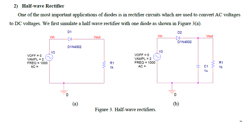
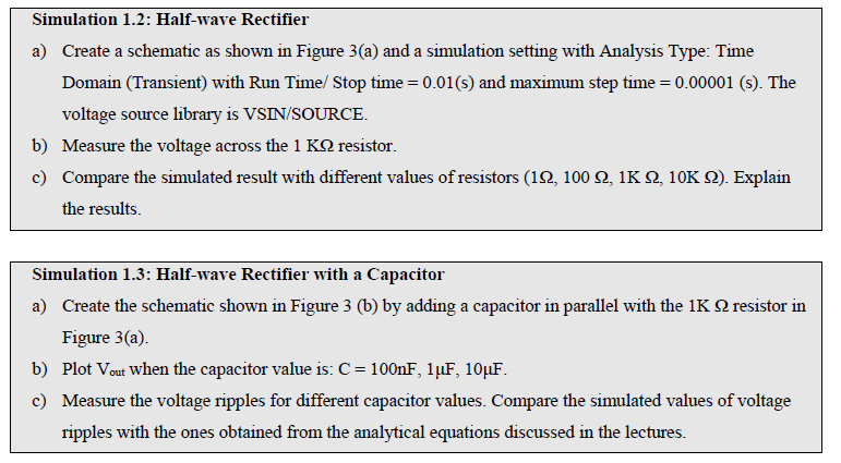
D2 2) Half-wave Rectifier One of the most important applications of diodes is in rectifier circuits which are used to convert AC voltages to DC voltages. We first simulate a half-wave rectifier with one diode as shown in Figure 3(a). D1 Vin N. Vout D1N4002 D1N4002 I v3 VOFF = 0 VAMPL = 2 VAMPL = 2 FREQ = 1000 FREQ = 1000 AC = AC = C13 Vin VOFF = 0 R1 0 o Figure 3. Half-wave rectifiers. Simulation 1.2: Half-wave Rectifier a) Create a schematic as shown in Figure 3(a) and a simulation setting with Analysis Type: Time Domain (Transient) with Run Time Stop time=0.01(s) and maximum step time=0.00001 (s). The voltage source library is VSIN/SOURCE. b) Measure the voltage across the 1 KS resistor. c) Compare the simulated result with different values of resistors (12, 100 2,1K 2, 10K 12). Explain the results. Simulation 1.3: Half-wave Rectifier with a Capacitor a) Create the schematic shown in Figure 3 (b) by adding a capacitor in parallel with the 1K resistor in Figure 3(a). b) Plot Vout when the capacitor value is: C = 100nF, 1uF, 10uF. c) Measure the voltage ripples for different capacitor values. Compare the simulated values of voltage ripples with the ones obtained from the analytical equations discussed in the lectures. D2 2) Half-wave Rectifier One of the most important applications of diodes is in rectifier circuits which are used to convert AC voltages to DC voltages. We first simulate a half-wave rectifier with one diode as shown in Figure 3(a). D1 Vin N. Vout D1N4002 D1N4002 I v3 VOFF = 0 VAMPL = 2 VAMPL = 2 FREQ = 1000 FREQ = 1000 AC = AC = C13 Vin VOFF = 0 R1 0 o Figure 3. Half-wave rectifiers. Simulation 1.2: Half-wave Rectifier a) Create a schematic as shown in Figure 3(a) and a simulation setting with Analysis Type: Time Domain (Transient) with Run Time Stop time=0.01(s) and maximum step time=0.00001 (s). The voltage source library is VSIN/SOURCE. b) Measure the voltage across the 1 KS resistor. c) Compare the simulated result with different values of resistors (12, 100 2,1K 2, 10K 12). Explain the results. Simulation 1.3: Half-wave Rectifier with a Capacitor a) Create the schematic shown in Figure 3 (b) by adding a capacitor in parallel with the 1K resistor in Figure 3(a). b) Plot Vout when the capacitor value is: C = 100nF, 1uF, 10uF. c) Measure the voltage ripples for different capacitor values. Compare the simulated values of voltage ripples with the ones obtained from the analytical equations discussed in the lectures
Step by Step Solution
There are 3 Steps involved in it

Get step-by-step solutions from verified subject matter experts