

Question: Description of the design problem Deakin University is developing a mobile Gantry Crane for the new Hycel Technology Hub. All team Members have developed an
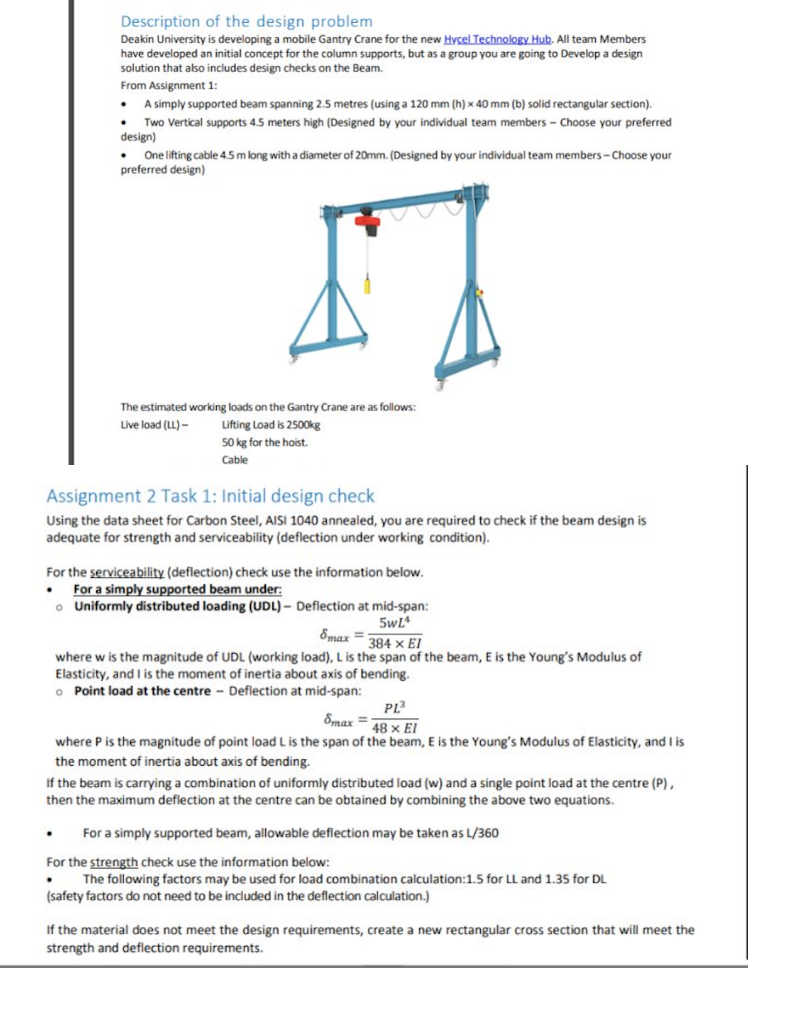
Description of the design problem Deakin University is developing a mobile Gantry Crane for the new Hycel Technology Hub. All team Members have developed an initial concept for the column supports, but as a group you are going to Develop a design solution that also includes design checks on the Beam. From Assignment 1: - A simply supported beam spanning 2.5 metres (using a 120mm(h)40mm (b) solid rectangular section). - Two Vertical supports 4.5 meters high (Designed by your individual team members - Choose your preferred design) - One lifting cable 4.5m long with a diameter of 20mm. (Designed by your individual team members - Choose your preferred design) The estimated working loads on the Gantry Crane are as follows: Live load (UL) - Lifting Load is 2500kg 50kg for the hoist. Cable Assignment 2 Task 1: Initial design check Using the data sheet for Carbon Steel, AISI 1040 annealed, you are required to check if the beam design is adequate for strength and serviceability (deflection under working condition). For the serviceability (deflection) check use the information below. - For a simply supported beam under: Uniformly distributed loading (UDL) - Deflection at mid-span: max=384EI5wL4 where w is the magnitude of UDL (working load), L is the span of the beam, E is the Young's Modulus of Elasticity, and I is the moment of inertia about axis of bending. - Point load at the centre - Deflection at mid-span: max=48EIPL3 where P is the magnitude of point load L is the span of the beam, E is the Young's Modulus of Elasticity, and I is the moment of inertia about axis of bending. If the beam is carrying a combination of uniformly distributed load ( w) and a single point load at the centre (P), then the maximum deflection at the centre can be obtained by combining the above two equations. - For a simply supported beam, allowable deflection may be taken as L/360 For the strength check use the information below: The following factors may be used for load combination calculation: 1.5 for LL and 1.35 for DL (safety factors do not need to be included in the deflection calculation.) If the material does not meet the design requirements, create a new rectangular cross section that will meet the strength and deflection requirements
Step by Step Solution
There are 3 Steps involved in it

Get step-by-step solutions from verified subject matter experts