

Question: Design a 2-bit ripple carry adder using the full adder designed in the previous step. Consult Figure 3 for guidance. Your digital circuit should have
Design a 2-bit ripple carry adder using the full adder designed in the previous step. Consult Figure 3 for guidance. Your digital circuit should have two 2-bit inputs, {A1, A0} and {B1, B0}, and one single bit input, {Cin}. Similarly, it should have a 2-bit output, {S1 S0}, and a single bit output, {Cout}. Provide the truth table for the 2-bit adder. You do not have to compute the boolean expressions. Draw the gate-level schematic for the 2-bit ripple carry adder. Edit: I have the Truth table and the figure below that I made I just need help with the gate level schematic. Thanks again for the help :)
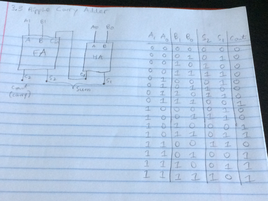
3.3 Ripple Carry AI C2 cont (cany) 81 FA Adder Sum AD A HA A, A B, B 5 HOOOOoooo I SHH 1 1 1 1 1 1 PHOOO0 1 1 a 1 11 1 PT HOLLOON HOOLHOONH 1 1 1 1 2 0 O 01 1 1 1 O HOHOHOHOH 1 1 ONO 01 1 00 1 O 1 Q 1 10 O HOOH S Cont TO HOT HO 1 OF ON POPROP 1 1 10 OG OG GO LLLOLEOCHI 1 1 1
Step by Step Solution
3.48 Rating (148 Votes )
There are 3 Steps involved in it
Ripple Carry A B C A B Cin A B 44 FA H... View full answer

Get step-by-step solutions from verified subject matter experts