

Question: Design a circuit that has two inputs, clk and X, and produces one output O. X may change every clock cycle and the change happens
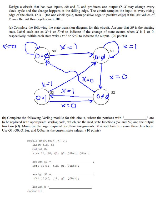
Design a circuit that has two inputs, clk and X, and produces one output O. X may change every clock cycle and the change happens at the falling edge. The circuit samples the input at every rising edge of the clock. O is 1 (for one clock cycle, from positive edge to positive edge) if the last values of X over the last three cycles were 101 (a) Complete the following the state transition diagram for this circuit. Assume that SO is the starting state. Label each arc as X=1 or X=0 to indicate if the change of state occurs when X s 1 or 0, respectively. Within each state write O-I or O-0 to indicate the output. (20 points) XTO SO Si 0 S3 S2 0f (b) Complete the following Verilog module for this circuit, where the portions with ". to be replaced with appropriate Verilog code, which are the next state functions (SI and S0) and the output function ( Minimize the logic required for these assignments. You will have to derive these functions. Use Q1, Q0, Qlbar, and Q0bar as the current state values. (10 points) arc module HW9P2 (clk, x, o) input clk, x; output O wire S1, s0, 91, 00, Qlbar, 00bar assign s1 Dffi ci (S1, clk, Q1, Qlbar) assign S0 Dffi co (s0, clk, Q0, Q0bar) assign o
Step by Step Solution
There are 3 Steps involved in it

Get step-by-step solutions from verified subject matter experts