

Question: Design Exercise # 1 Specification In the system shown below in Figure 1 , a shaft carries 3 gears ( at locations B , C
Design Exercise # Specification
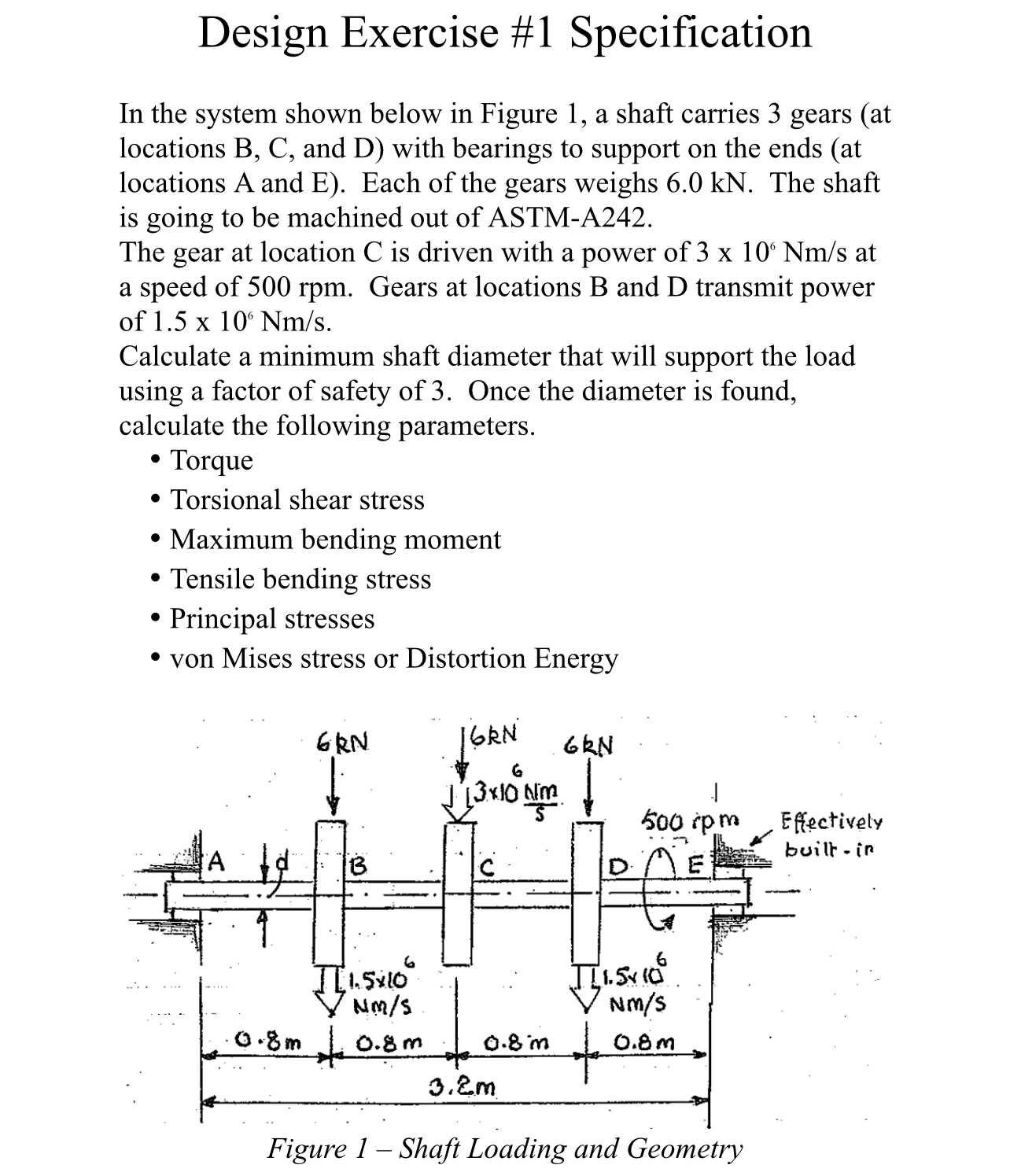
In the system shown below in Figure a shaft carries gears at locations B C and D with bearings to support on the ends at locations A and E Each of the gears weighs kN The shaft is going to be machined out of ASTMA
The gear at location C is driven with a power of at a speed of rpm Gears at locations B and D transmit power of
Calculate a minimum shaft diameter that will support the load using a factor of safety of Once the diameter is found, calculate the following parameters.
Torque
Torsional shear stress
Maximum bending moment
Tensile bending stress
Principal stresses
von Mises stress or Distortion Energy
Step by Step Solution
There are 3 Steps involved in it
1 Expert Approved Answer
Step: 1 Unlock

Question Has Been Solved by an Expert!
Get step-by-step solutions from verified subject matter experts
Step: 2 Unlock
Step: 3 Unlock