

Question: Develop a Plot Plan for the Coker Unit as represented in Module 4 HW 2 PFD.pdf. Show a plan (top) view of each equipment
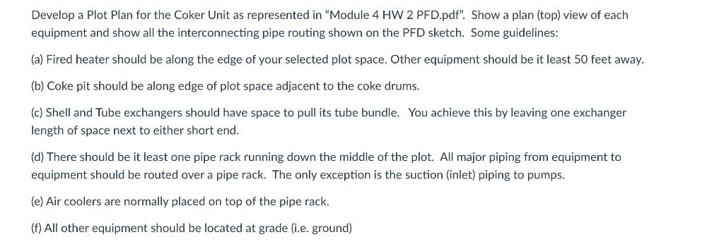
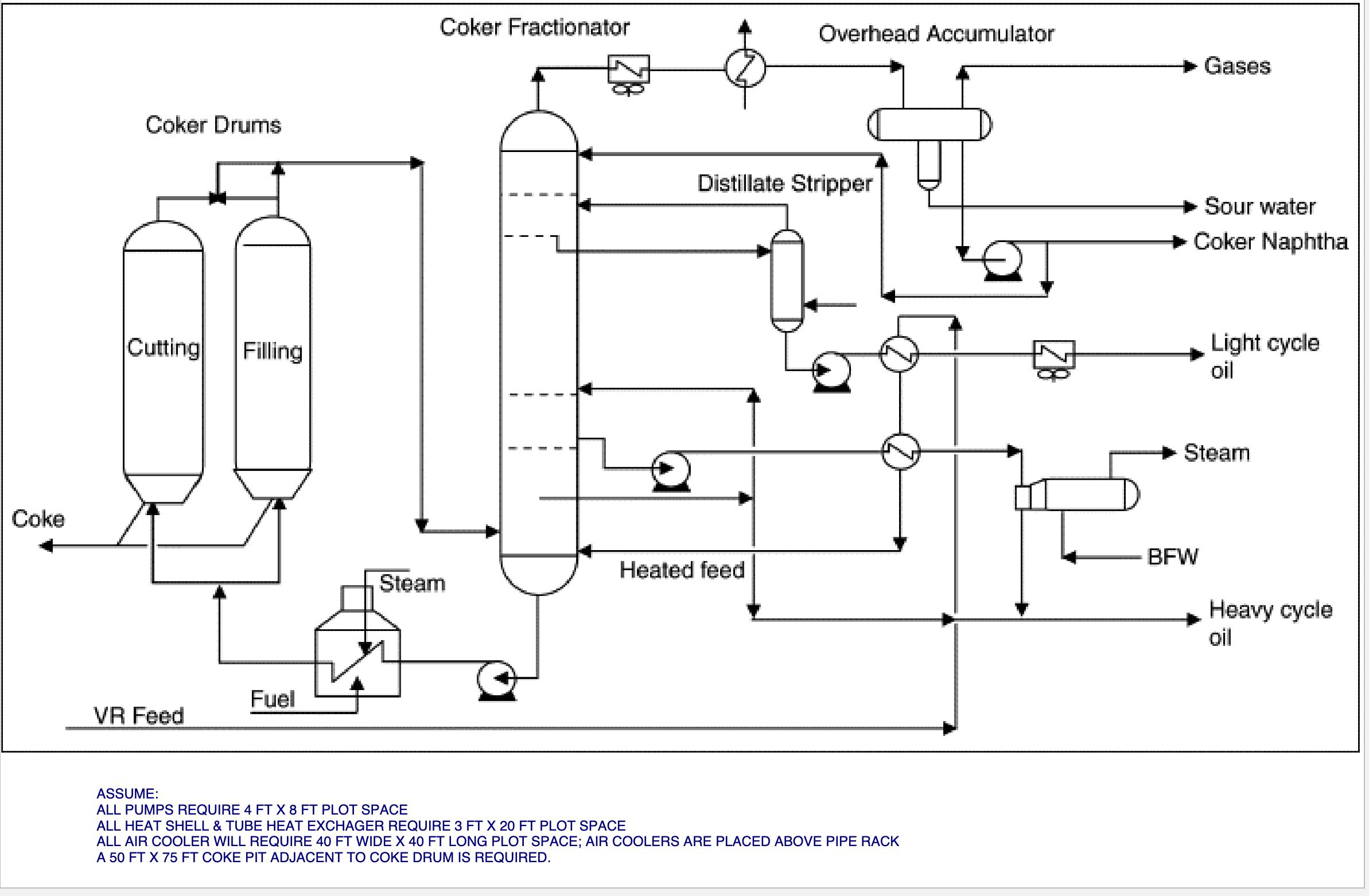

Develop a Plot Plan for the Coker Unit as represented in "Module 4 HW 2 PFD.pdf". Show a plan (top) view of each equipment and show all the interconnecting pipe routing shown on the PFD sketch. Some guidelines: (a) Fired heater should be along the edge of your selected plot space. Other equipment should be it least 50 feet away. (b) Coke pit should be along edge of plot space adjacent to the coke drums. (c) Shell and Tube exchangers should have space to pull its tube bundle. You achieve this by leaving one exchanger length of space next to either short end.. (d) There should be it least one pipe rack running down the middle of the plot. All major piping from equipment to equipment should be routed over a pipe rack. The only exception is the suction (inlet) piping to pumps. (e) Air coolers are normally placed on top of the pipe rack. (f) All other equipment should be located at grade (i.e. ground) Coke Coker Drums Cutting Filling Fuel VR Feed Coker Fractionator Overhead Accumulator Gases Distillate Stripper Sour water Coker Naphtha Light cycle oil Steam BFW Heated feed Steam Heavy cycle oil ASSUME: ALL PUMPS REQUIRE 4 FT X 8 FT PLOT SPACE ALL HEAT SHELL & TUBE HEAT EXCHAGER REQUIRE 3 FT X 20 FT PLOT SPACE ALL AIR COOLER WILL REQUIRE 40 FT WIDE X 40 FT LONG PLOT SPACE; AIR COOLERS ARE PLACED ABOVE PIPE RACK A 50 FT X 75 FT COKE PIT ADJACENT TO COKE DRUM IS REQUIRED. COKE DRUMS 20 FT DIA X 95 FT T/T HEATER 25 FT DIA X 50 FT HEIGHT FRACTIONATOR 15 FT DIA X 120 FT T/T STRIPPER 3 FT DIA X 60 FT T/T ACCUMULATR 8 FT DIA X 25 FT T/T
Step by Step Solution
There are 3 Steps involved in it

Get step-by-step solutions from verified subject matter experts