Question: Digital Logic Design A combinational circuit for a 4-variable logic circuit F(A,B,C,D) is given in the circuit diagram that follows. If the signal waveforms for
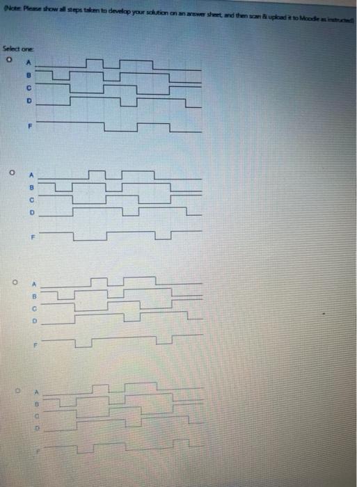
A combinational circuit for a 4-variable logic circuit F(A,B,C,D) is given in the circuit diagram that follows. If the signal waveforms for all inputs A, B, C. and D are given as shown in the timing diagram below. then the output waveform for F can be: B D UL (Note: Please show all steps taken to develop your solution on an answer sheet and then scan & upload it to Moodle as instructed) Net Pestowall steps to develop your dution on answer sheet and then upload to Moede Select one o B 0 Using a decoder and some external gates, a combinational circuit with three inputs Ag, Ay, and Ag and two outputs X(Ay, Az. Ao) and Y(Ag, Au, Ao) is implemented as shown in the circuit diagram that follows. If the signal waveforms for all inputs are given as shown in the timing diagram below, then the output waveforms for X and Y can be 3x Decoder AL? A. Y (Note: Please show all steps taken to develop your solution on an answer sheet and then scan upload it to Moodle as instructed) Select one: (Note: Please show steps tom to develop your solution on what and then som brukad to Moodles Select one A 4-variable logic function Y(A3, A3, A1, ) is implemented using a 4x1 multiplexer (4x7 MUX) and some external gates as shown in the circuit diagram that follows. If the waveforms for all inputs are given as shown in the timing diagram below, then the output waveform for Y can be (Note: Please show all steps taken to develop your solution on an answer sheet, and then scan & upload to Moodle as instructed) Select one: Note: Please show all steps taken to develop your solution on an ower sheet, and then scan upload to Moode as instructed Select one P2