

Question: Draw a flawchart for this Real-time alarm digital clock Read the requirements carefully and make a flawchart for the digital alarm clock look at the
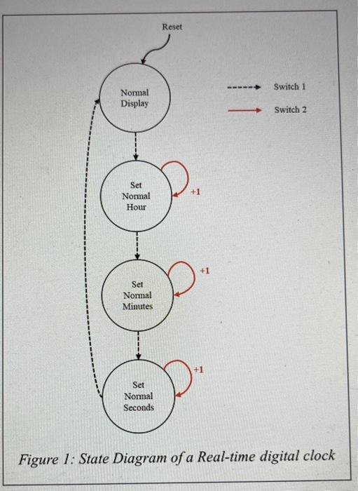
You are required to design a digital alarm clock using the S7G2-SK. The basic clock's functionality follows the State Transition Diagram in Figure 1. As there are no audible outputs on these boards, use two LEDs that flash alternately to signify an alarm condition. Use a third LED to give a visual output as to when the alarm is in a set condition. The alarm clock is limited to using two buttons to change the mode of operation, as indicated in State Transition Diagram. You are required to implement the alarm functionality in addition to the normal clock where the alarm clock's alarm can only be set or cleared in the 'Normal Display' state; this is the only state that the alarm condition can be activated, which would require the alarm to be set and the actual time to match the alarm time. (The alarm functionality is not indicated in the state transition diagram) If the alarm has been activated then any of the two buttons will stop the alarm, taking it out of the set condition. If the alarm is not stopped by user interaction, then after one minute the alarm clock will automatically stop the LEDs toggling, again taking it out of a set condition. Figur ick
Step by Step Solution
There are 3 Steps involved in it

Get step-by-step solutions from verified subject matter experts