Question: DRAWING DATA FLOW DIAGRAM FINAL GRADE SUBMITTED WORK STUDENT RECORDS SYSTEM STUDENT 0 CLASS ROSTER GRADED WORK When drawing a context diagram and other DFDs,
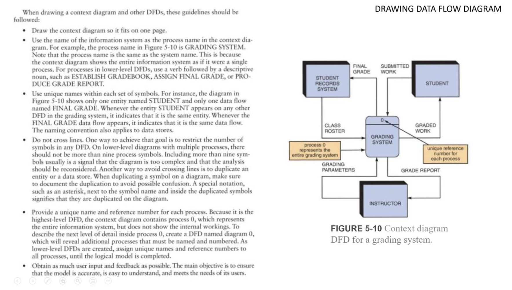
DRAWING DATA FLOW DIAGRAM FINAL GRADE SUBMITTED WORK STUDENT RECORDS SYSTEM STUDENT 0 CLASS ROSTER GRADED WORK When drawing a context diagram and other DFDs, these guidelines should be followed: Draw the context diagram so it fits on one page. Use the name of the information system as the process name in the context dia- gram. For example, the process name in Figure 5-10 is GRADING SYSTEM. Note that the process name is the same as the system name. This is because the context diagram shows the entire information system as if it were a single process. For processes in lower-level DFDs, use a verb followed by a descriptive noun, such as ESTABLISH GRADEBOOK, ASSIGN FINAL GRADE, or PRO- DUCE GRADE REPORT. Use unique names within each set of symbols. For instance, the diagram in Figure 5-10 shows only one entity named STUDENT and only one data flow named FINAL GRAD. Whenever the entity STUDENT appears on any other DFD in the grading system, it indicates that it is the same entity. Whenever the FINAL GRADE data flow appears, it indicates that it is the same data flow. The naming convention also applies to data stores. Do not cross lines. One way to achieve that goal is to restrict the number of symbols in any DFD. On lower-level diagrams with multiple processes, there should not be more than nine process symbols. Including more than nine sym- bols usually is a signal that the diagram is too complex and that the analysis should be reconsidered. Another way to avoid crossing lines is to duplicate an entity or a data store. When duplicating a symbol on a diagram, make sure to document the duplication to avoid possible confusion. A special notation, such as an asterisk, next to the symbol name and inside the duplicated symbols signifies that they are duplicated on the diagram. Provide a unique name and reference number for each process. Because it is the highest-level DFD, the context diagram contains process 0, which represents the entire information system, but does not show the internal workings. To describe the next level of detail inside process 0, create a DFD named diagram 0, which will reveal additional processes that must be named and numbered. As lower-level DFDs are created, assign unique names and reference numbers to all processes, until the logical model is completed. Obtain as much user input and feedback as possible. The main objective is to ensure that the model is accurate, is easy to understand, and meets the needs of its users. GRADING SYSTEM process o represents the entire grading system GRADING PARAMETERS unique reference number for each process GRADE REPORT INSTRUCTOR FIGURE 5-10 Context diagram DFD for a grading system


