

Question: Due Date: 5 / 1 2 / 2 0 2 4 Consider the following closed - loop control system: Figure 1 : Block Diagram of
Due Date:
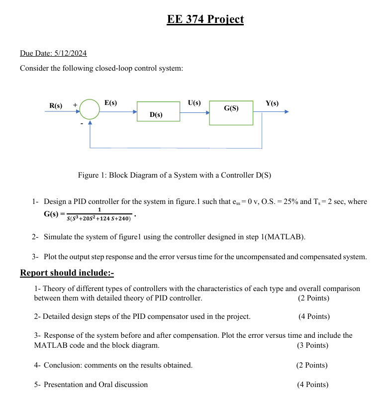
Consider the following closedloop control system:
Figure : Block Diagram of a System with a Controller DS
Design a PID controller for the system in figure. such that mathrmemathrmSsmathrmvmathrmOmathrmS and mathrmTmathrmsmathrmsec where GsfracSleftS S Sright
Simulate the system of figure using the controller designed in step MATLAB
Plot the output step response and the error versus time for the uncompensated and compensated system.
Report should include:
Theory of different types of controllers with the characteristics of each type and overall comparison between them with detailed theory of PID controller.
Points
Detailed design steps of the PID compensator used in the project.
Points
Response of the system before and after compensation. Plot the error versus time and include the MATLAB code and the block diagram.
Points
Conclusion: comments on the results obtained.
Points
Presentation and Oral discussion
Points
Step by Step Solution
There are 3 Steps involved in it
1 Expert Approved Answer
Step: 1 Unlock

Question Has Been Solved by an Expert!
Get step-by-step solutions from verified subject matter experts
Step: 2 Unlock
Step: 3 Unlock