

Question: exam! please help!! Consider the universal shift register with an Asynchronous parallel load shown in the following figure: Q- Q. Q: Q: Q: Q: Q,
exam! please help!!
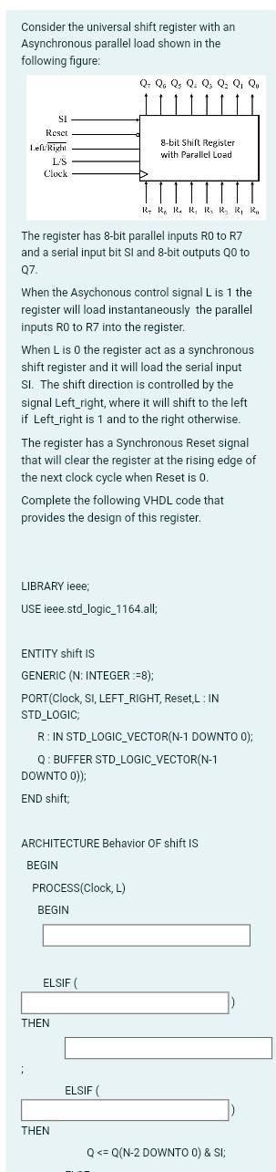
Consider the universal shift register with an Asynchronous parallel load shown in the following figure: Q- Q. Q: Q: Q: Q: Q, Qo SI Reset Left: Right L'S Clock 8-bit Shill Register with Parallel Load R.RRRRRRR The register has 8-bit parallel inputs RO to R7 and a serial input bit Sl and 8-bit outputs Q0 to 07 When the Asychonous control signal L is 1 the register will load instantaneously the parallel inputs RO to R7 into the register. When L is the register act as a synchronous shift register and it will load the serial input SI. The shift direction is controlled by the signal Left_right, where it will shift to the left if Left_right is 1 and to the right otherwise. The register has a Synchronous Reset signal that will clear the register at the rising edge of the next clock cycle when Reset is 0. Complete the following VHDL code that provides the design of this register. LIBRARY ieee; USE ieee.std_logic_1164.all; ENTITY shift is GENERIC (N: INTEGER :=8); PORT(Clock, SI, LEFT_RIGHT, Reset,L: IN STD_LOGIC; R: IN STD_LOGIC_VECTOR(N-1 DOWNTO 0); Q: BUFFER STD_LOGIC_VECTOR(N-1 DOWNTO O)); END shift ARCHITECTURE Behavior of shift is BEGIN PROCESS(Clock, L) BEGIN ELSIF THEN ELSIF THEN Q
Step by Step Solution
There are 3 Steps involved in it

Get step-by-step solutions from verified subject matter experts