

Question: Example 1. Implementation of a Synchronous Up - Counter Worked by: Instructor of ECET:46 F. F2 Input Logical 1 1 Ta-FF Tb-FF Tc-FF Td-FF Qa
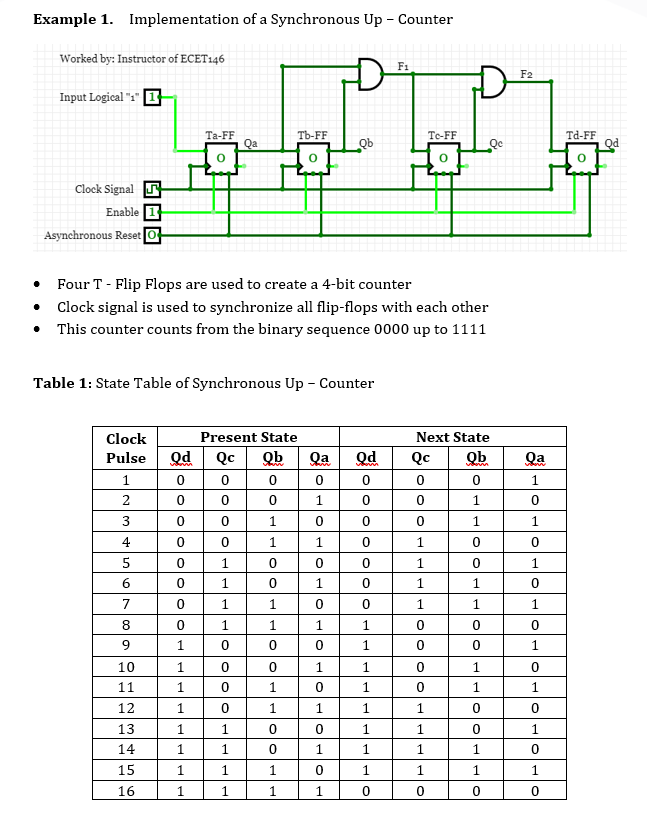
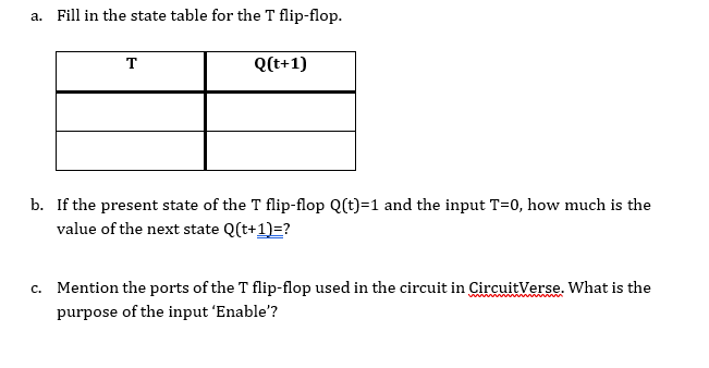
Example 1. Implementation of a Synchronous Up - Counter Worked by: Instructor of ECET:46 F. F2 Input Logical "1" 1 Ta-FF Tb-FF Tc-FF Td-FF Qa Qb Qc Qd Clock Signal I Enable Asynchronous Reset O Four T - Flip Flops are used to create a 4-bit counter Clock signal is used to synchronize all flip-flops with each other This counter counts from the binary sequence 0000 up to 1111 Table 1: State Table of Synchronous Up - Counter Qd Clock Pulse 1 2 Present State Qd Q Qb 0 0 0 0 0 0 0 1 Qa 0 1 Next State Q Qb 0 0 1 Qa 1 0 0 0 3 0 0 1 1 4 0 1 1 0 1 0 0 0|0||0|0 1 0 0 1 5 6 7 1 0 1 1 0 1 1 0 1 1 0 0 0 0 1 1 1 1 1 8 0 1 1 1 0 0 0 0 9 1 0 0 0 0 1 1 0 0 1 1 0 0 1 1 1 0 1 0 1 0 1 1 0 1 1 1 1 0 0 10 11 12 13 14 15 1 1 0 0 1 1 1 0 1 1 1 0 1 1 1 0 1 1 1 0 1 1 1 1 16 1 1 1 1 0 0 0 0 a. Fill in the state table for the T flip-flop. T Q(t+1) b. If the present state of the T flip-flop Q(t)=1 and the input T=0, how much is the value of the next state Q(t+1)=? C. Mention the ports of the T flip-flop used in the circuit in CircuitVerse. What is the purpose of the input 'Enable
Step by Step Solution
There are 3 Steps involved in it

Get step-by-step solutions from verified subject matter experts