

Question: Exercise 1 8 . 1 . An x - y plane CAD drawing of a beam section is shown at right. The CAD program's analysis
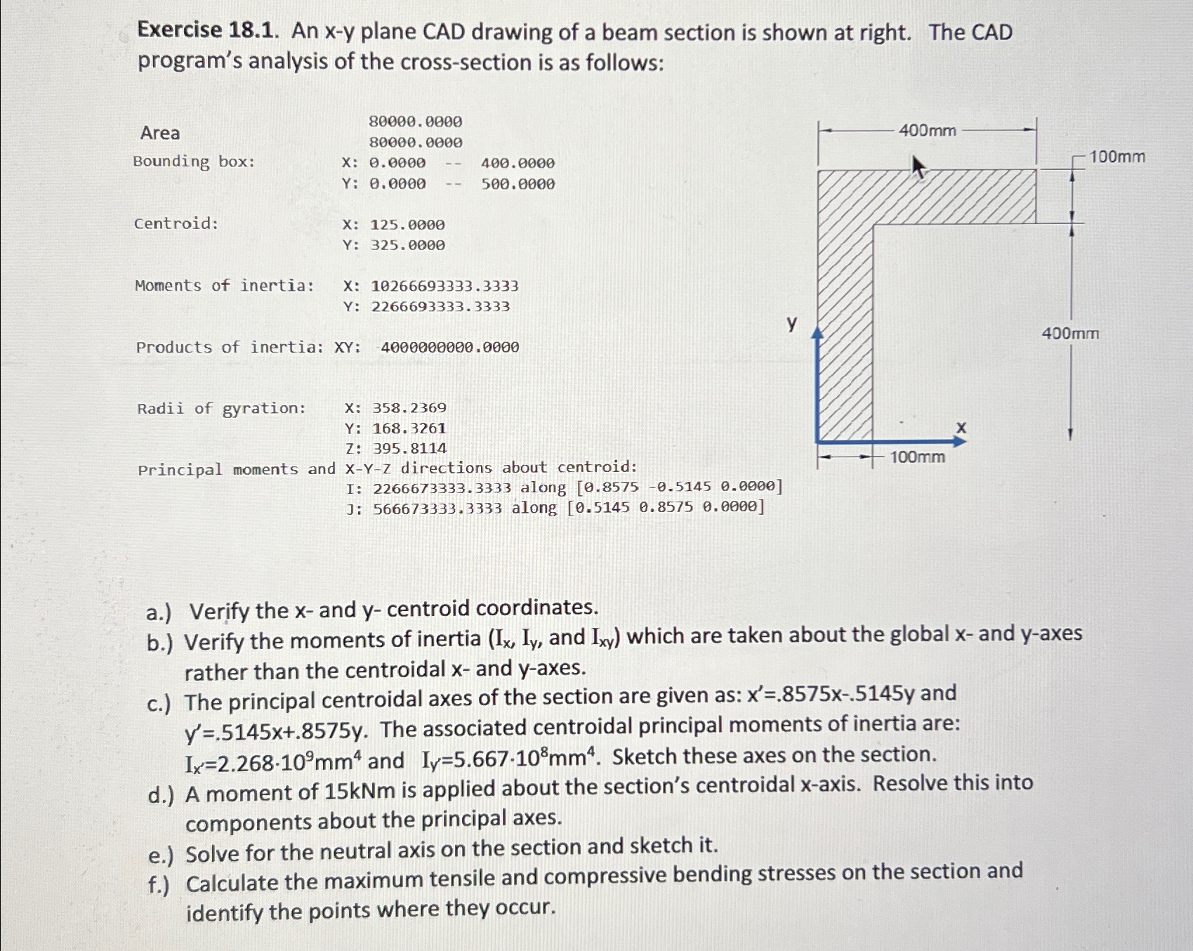
Exercise An plane CAD drawing of a beam section is shown at right. The CAD program's analysis of the crosssection is as follows:
Area
Bounding box:
Centroid:
Moments of inertia:
X:
Y:
Products of inertia: XY:
Radii of gyration:
:
:
:
Principal moments and directions about centroid:
a Verify the and centroid coordinates.
b Verify the moments of inertia and which are taken about the global and axes rather than the centroidal and axes.
c The principal centroidal axes of the section are given as: and The associated centroidal principal moments of inertia are: and Sketch these axes on the section.
d A moment of is applied about the sections centroidal axis. Resolve this into components about the principal axes.
e Solve for the neutral axis on the section and sketch it
f Calculate the maximum tensile and compressive bending stresses on the section and identify the points where they occur.
Step by Step Solution
There are 3 Steps involved in it
1 Expert Approved Answer
Step: 1 Unlock

Question Has Been Solved by an Expert!
Get step-by-step solutions from verified subject matter experts
Step: 2 Unlock
Step: 3 Unlock