

Question: In this session, we study Op-amp based integrators and differentiators, and transient analysis of RLC circuits in parallel and in series. Corresponding software exercises
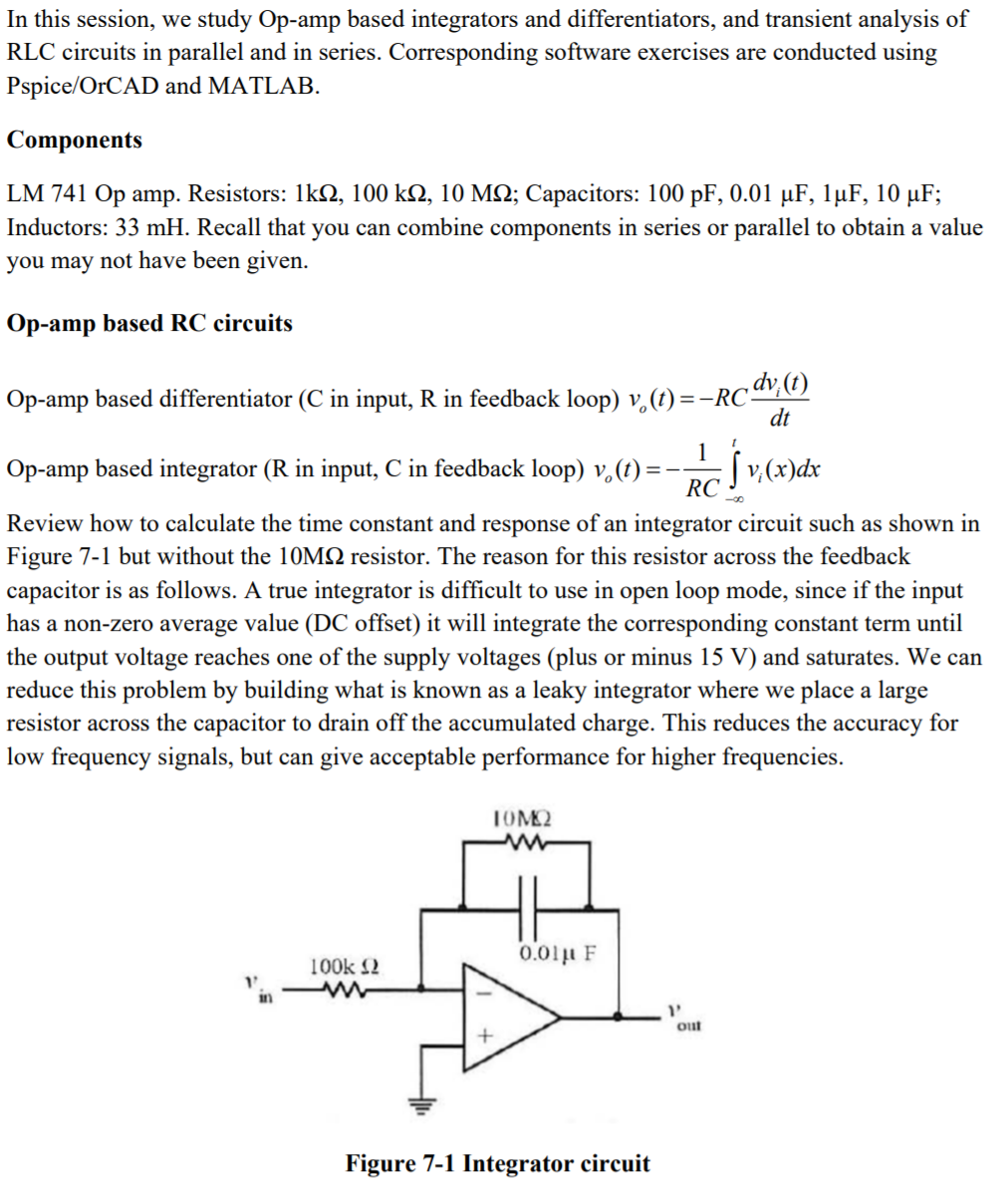
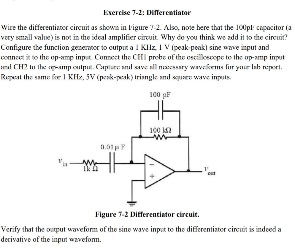
In this session, we study Op-amp based integrators and differentiators, and transient analysis of RLC circuits in parallel and in series. Corresponding software exercises are conducted using Pspice/OrCAD and MATLAB. Components LM 741 Op amp. Resistors: 1k, 100 km, 10 MM; Capacitors: 100 pF, 0.01 F, 1F, 10 F; Inductors: 33 mH. Recall that you can combine components in series or parallel to obtain a value you may not have been given. Op-amp based RC circuits Op-amp based differentiator (C in input, R in feedback loop) v. (t) = =-RC. ~dv;(t) dt 1 1 Op-amp based integrator (R in input, C in feedback loop) v. (t) = - [v(x)dx RC Review how to calculate the time constant and response of an integrator circuit such as shown in Figure 7-1 but without the 10MQ resistor. The reason for this resistor across the feedback capacitor is as follows. A true integrator is difficult to use in open loop mode, since if the input has a non-zero average value (DC offset) it will integrate the corresponding constant term until the output voltage reaches one of the supply voltages (plus or minus 15 V) and saturates. We can reduce this problem by building what is known as a leaky integrator where we place a large resistor across the capacitor to drain off the accumulated charge. This reduces the accuracy for low frequency signals, but can give acceptable performance for higher frequencies. 42 0.01 F 100k 1' Figure 7-1 Integrator circuit 1' out Exercise 7-2: Differentiator Wire the differentiator circuit as shown in Figure 7-2. Also, note here that the 100pF capacitor (a very small value) is not in the ideal amplifier circuit. Why do you think we add it to the circuit? Configure the function generator to output a 1 KHz, 1 V (peak-peak) sine wave input and connect it to the op-amp input. Connect the CH1 probe of the oscilloscope to the op-amp input and CH2 to the op-amp output. Capture and save all necessary waveforms for your lab report. Repeat the same for 1 KHz, 5V (peak-peak) triangle and square wave inputs. 100 pF 100 www 0.01 F Figure 7-2 Differentiator circuit. Verify that the output waveform of the sine wave input to the differentiator circuit is indeed a derivative of the input waveform. M 1k 22 V out
Step by Step Solution
3.53 Rating (173 Votes )
There are 3 Steps involved in it
0 PR2 R1 V1 1... View full answer

Get step-by-step solutions from verified subject matter experts