

Question: -Experiment 5-Design and Implement Application circuits [Course Outcome: 3.6] Objectives The purpose of this experiment is to design and implement an application circuit based on
![-Experiment 5-Design and Implement Application circuits [Course Outcome: 3.6] Objectives The](https://dsd5zvtm8ll6.cloudfront.net/si.experts.images/questions/2024/09/66f52b6a2e889_46566f52b69b2c2c.jpg)
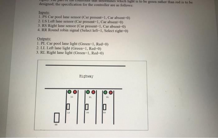
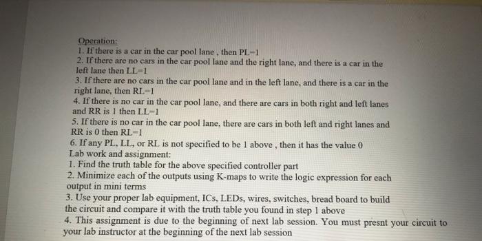
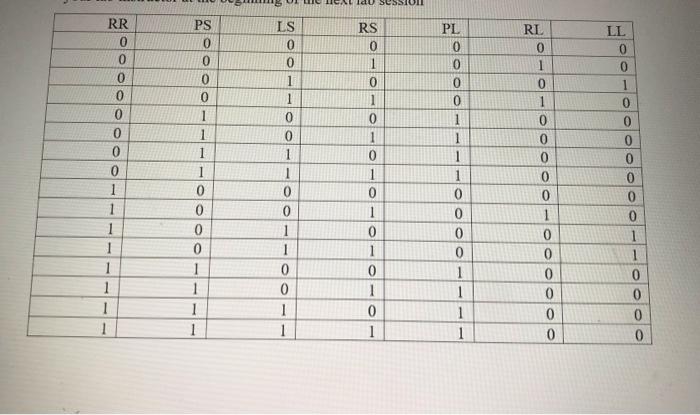
-Experiment 5-Design and Implement Application circuits [Course Outcome: 3.6] Objectives The purpose of this experiment is to design and implement an application circuit based on the problem description. Problem description A traffic metering system for controlling the release of traffic from an entrance ramp onto the high way has the following specifications for a part of its controller. There are three parallel metering lanes, each with its own lights (Red for Stop) and (Green for Go).One of these lanes is the car pool lane which is given the priority for green light over the other two lanes. Otherwise a Round Robin scheme in which the green lights alternate is used for other two lanes (left and right). The part of the controller that determines which light is to be green rather than red is to be designed; the specification for the controller are as follows: Inputs: 1. PS Car pool lane sensor (Car present=1, Car absent-0) 2. LS Left lane sensor (Car present=1, Car absent=0) 3. RS Right lane sensor (Car present-1, Car absent=0) 4. RR Round robin signal (Select left-1, Select right-0) Outputs: D. Focus A a aines which light is to be green rather than red is to be designed; the specification for the controller are as follows: Inputs: 1. PS Car pool lane sensor (Car present-1, Car absento) 2. LS Left lane sensor (Car present-1. Car absento) 3. RS Right lane sensor (Car present-1. Car absent-0) 4. RR Round robin signal (Select left-1, Select right-0) Outputs: 1. PL Car pool lane light (Green-1, Red-0) 2. LL Left lane light (Green-1, Red-0) 3. RL Right lane light (Green-1, Red-0) Highway VE RE 0 0 PS NS 0 Operation: 1. If there is a car in the car pool lane, then PL-1 2. If there are no cars in the car pool lane and the right lane, and there is a car in the left lane then LL=1 3. If there are no cars in the car pool lane and in the left lane, and there is a car in the right lane, then RI-1 4. If there is no car in the car pool lane, and there are cars in both right and left lanes and RR is I then LL-1 5. If there is no car in the car pool lane, there are cars in both left and right lanes and RR is 0 then RL-1 6. If any PL, LL, or RL is not specified to be 1 above, then it has the value 0 Lab work and assignment: 1. Find the truth table for the above specified controller part 2. Minimize each of the outputs using K-maps to write the logic expression for each output in mini terms 3. Use your proper lab equipment, ICs, LEDs, wires, switches, bread board to build the circuit and compare it with the truth table you found in step 1 above 4. This assignment is due to the beginning of next lab session. You must presnt your circuit to your lab instructor at the beginning of the next lab session do SESSION PS IS RR 0 PL RS 0 0 0 0 0 0 1 0 LL 0 0 1 0 0 0 0 1 1 0 0 0 0 1 0 0 0 0 0 0 0 0 1 1 0 0 0 1 0 1 0 1 0 1 1 1 1 1 0 0 0 0 1 1 1 1 1 1 1 1 1 1 1 1 0 RL 0 1 0 1 0 0 0 0 0 1 0 0 0 0 0 0 0 1 1 1 1 0 0 0 0 1 1 1 1 0 0 1 1 0 0 0 1 1 0 0 1 1 0 1 0 1 0
Step by Step Solution
There are 3 Steps involved in it

Get step-by-step solutions from verified subject matter experts