

Question: Experiment (6) Data Table Individual Resistors R8R = = 1190.5 22 R 8R = 1940.5 R3 8R3 = 376 0.52 Experiment (6) Data Table
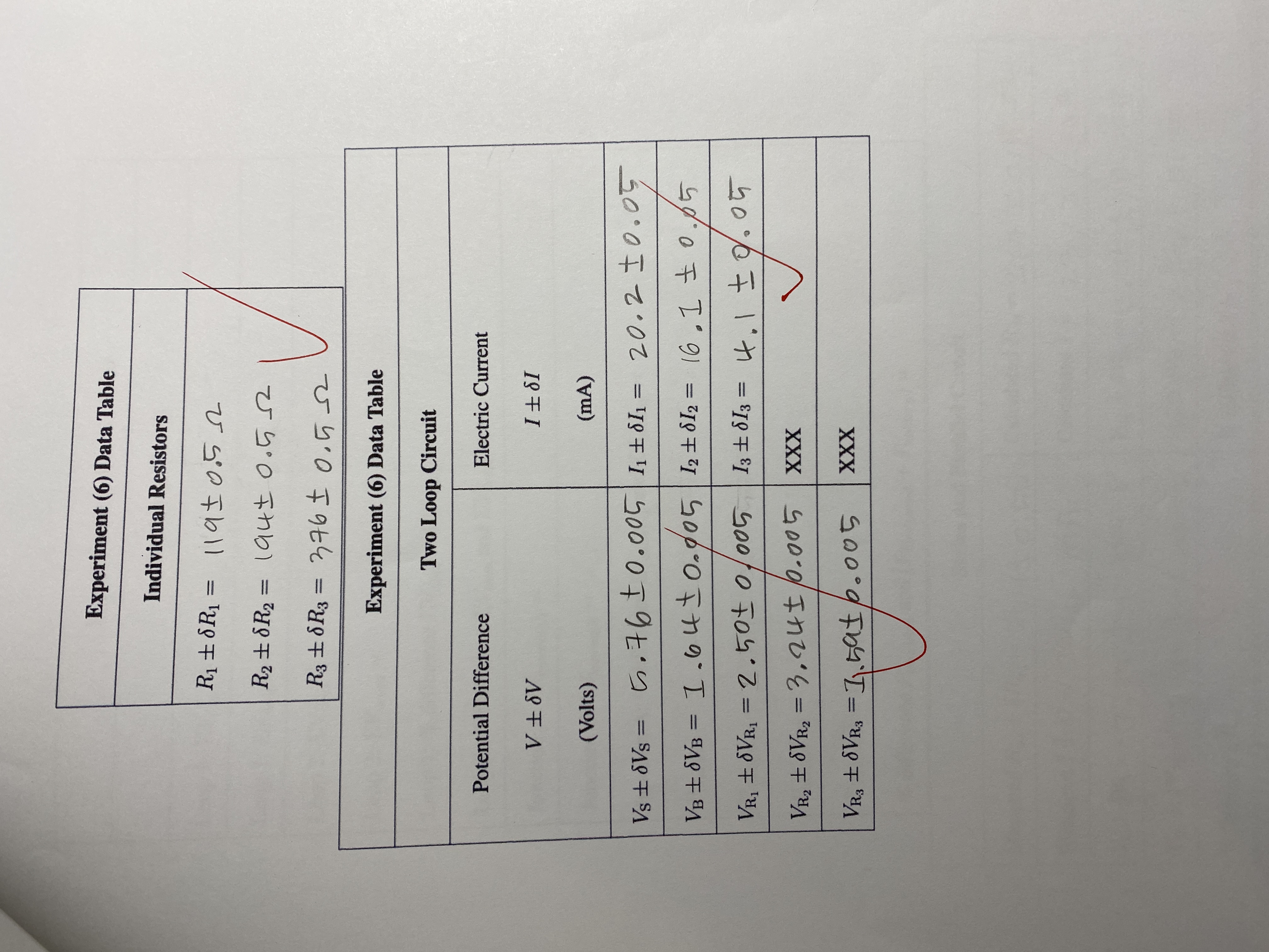
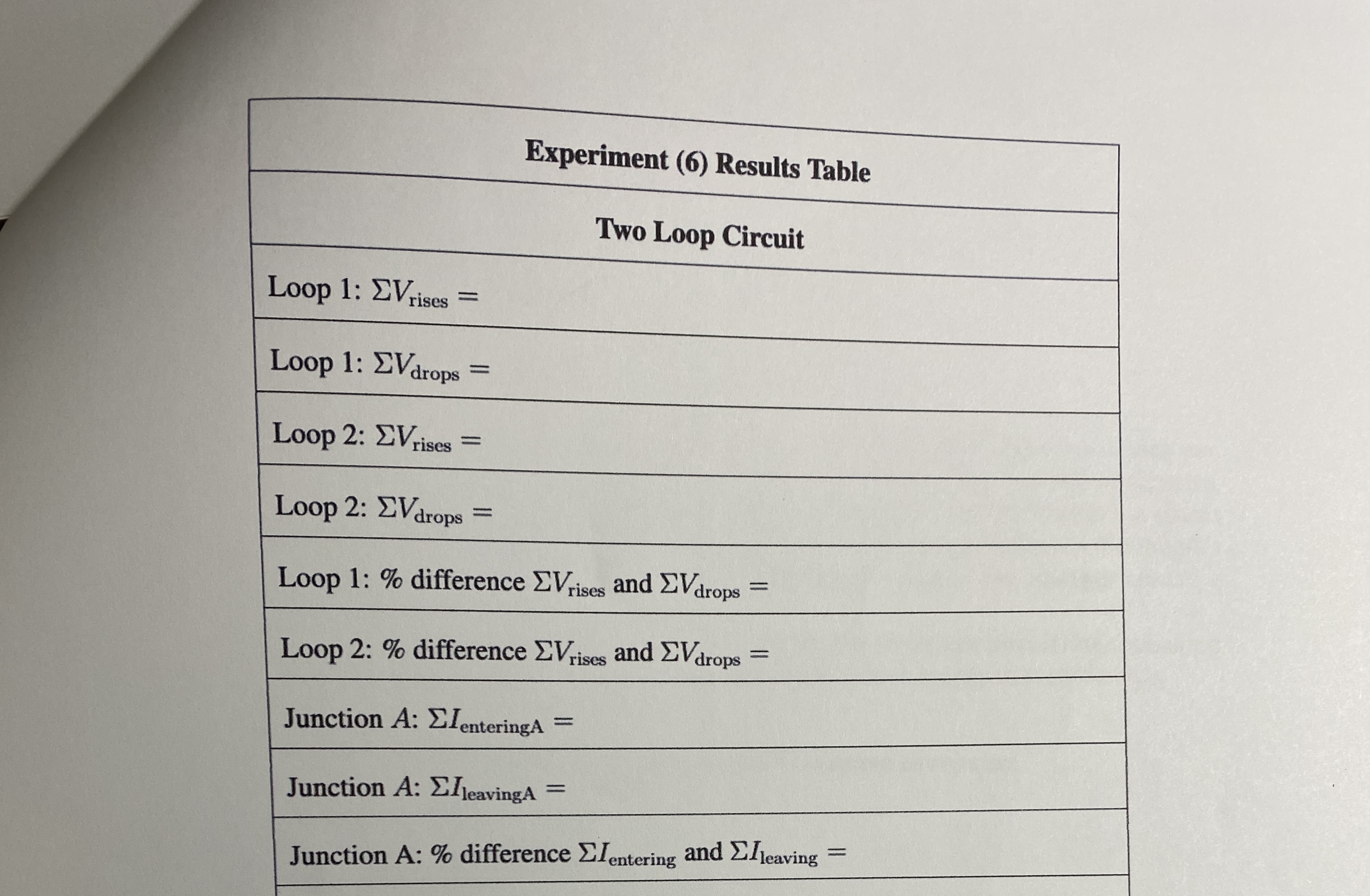

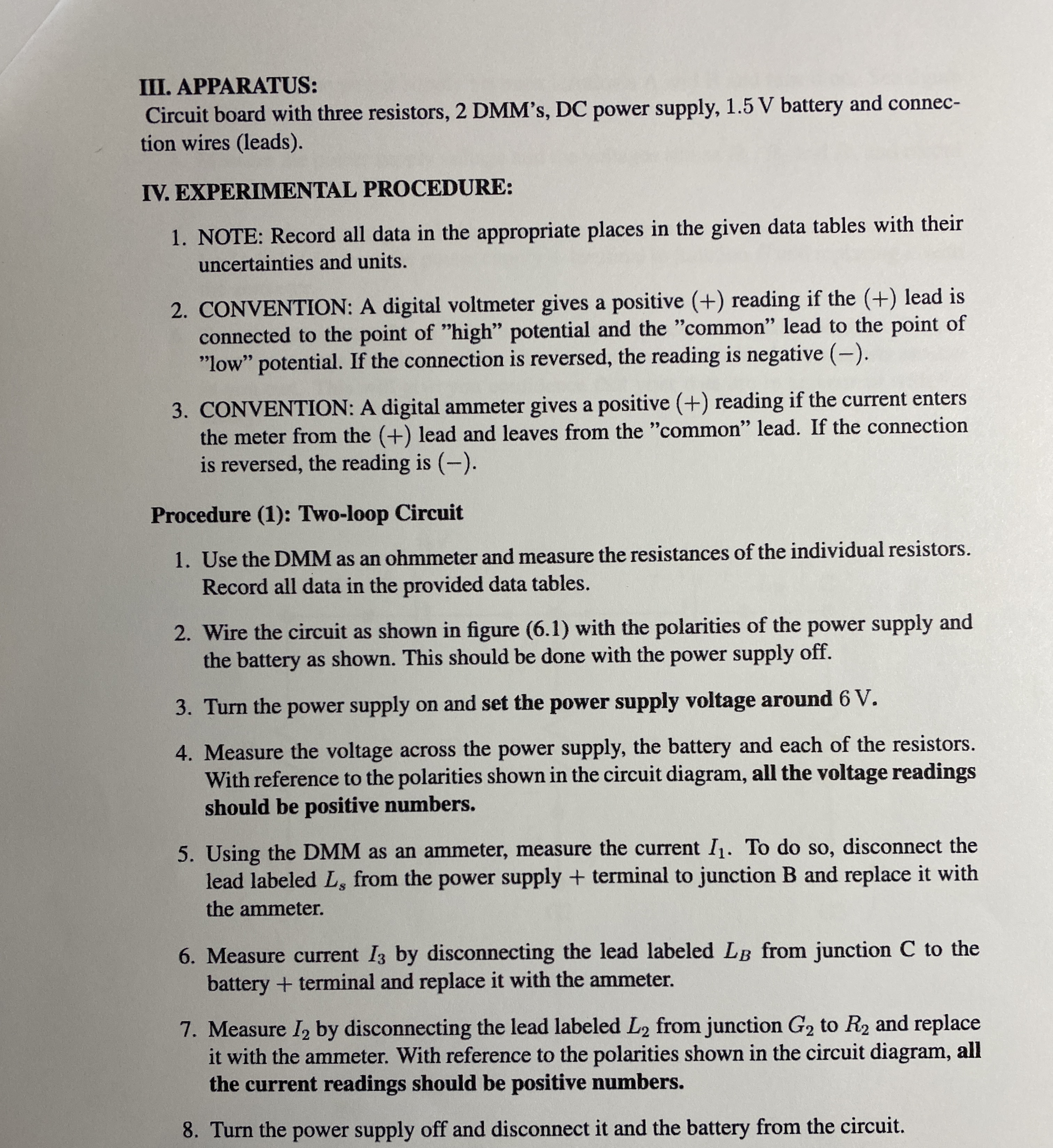
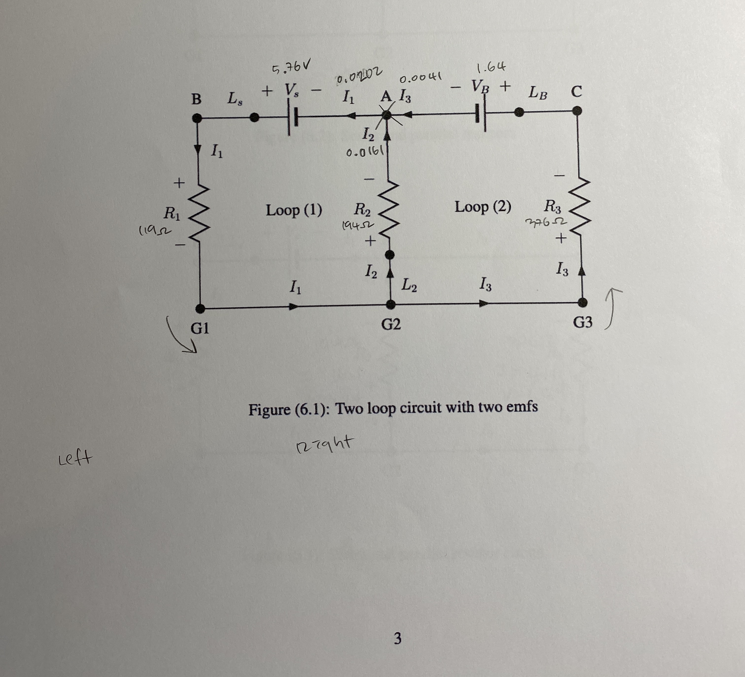
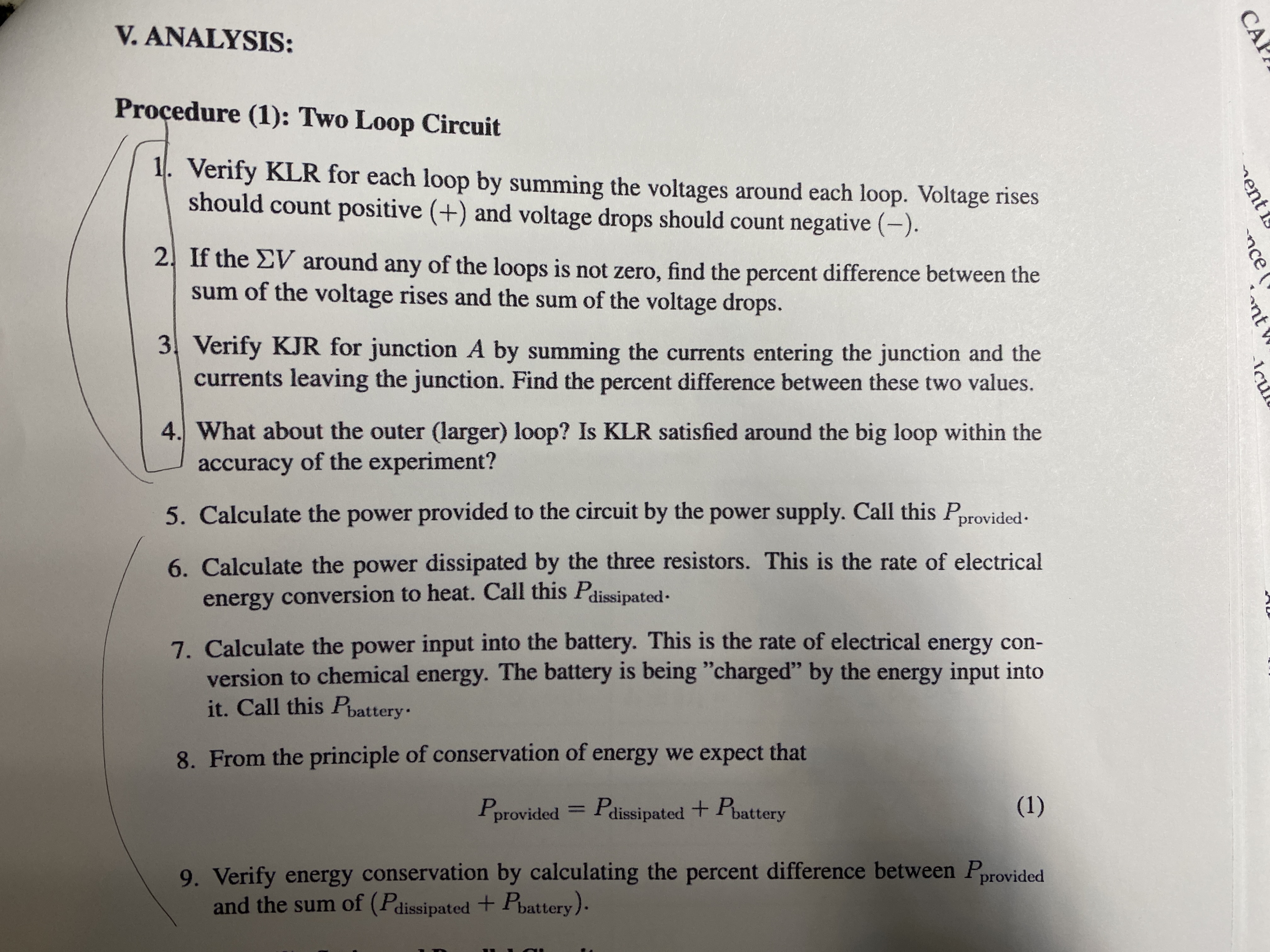
Experiment (6) Data Table Individual Resistors R8R = = 1190.5 22 R 8R = 1940.5 R3 8R3 = 376 0.52 Experiment (6) Data Table Two Loop Circuit Electric Current 181 Potential Difference VV (Volts) (mA) Vs6Vs = .760.005| 184 = 20.20.05 VB VB = 1.640.005 12812 = 16.1 0.05 VR 8VR = 2.50 0.005 | 13 813 = VR2 8VR2 = 3.24 0.005 XXX VR3 8VR3 = 11.596.005 XXX 4.1 0.05 Loop 1: Vrises = Loop 1: EV drops = Loop 2: Vrises = Loop 2: V drops = Experiment (6) Results Table Two Loop Circuit Loop 1: % difference Vrises and Vdrops Loop 2: % difference Vrises and V drops Junction A: EIenteringA Junction A: IleavingA = = = Junction A: % difference entering and I leaving = PHYS 2426 Engineering Physics II EXPERIMENT 6 DC RESISTANCE CIRCUITS I. OBJECTIVE: The objective of this experiment is to study two-loop DC resistive circuits containing two sources of emf. This will be done by measuring the values of the individual resistors, then wiring the circuit and measuring the currents through and voltages across the circuit elements. The experimental results will be compared with the predictions of Kirchhoff's rules governing sum of the currents at a junction and the sum of the voltages around a closed loop. Also in this experiment, we will study series and parallel resistance circuits by measuring equivalent resistances and the currents provided by the power supply to such circuits. II. THEORY: The two most common methods of analysis of DC resistive circuits are 1. Kirchhoff's rules. 2. Series and parallel methods. Kirchhoff's Rules 1. Kirchhoff's Loop Rule or KLR (KVL) which states: Around a closed loop, the sum of the voltage rises (assumed positive) and the voltage drops (assumed negative) is zero. This rule is a consequence of conservation of energy. 2. Kirchhoff's Junction Rule or KJR (KCL) which states: At a junction, the sum of the currents entering the junction is equal to the sum of the currents leaving the junction. This rule is a consequence of conservation of charge. 3. These are general rules which can be applied to any circuit. Their application to a two loop circuit for example allows us to write three algebraic equations involving the currents, voltages and resistances in the circuit. These three equations are: (a) one junction equation (KJR) and (b) two loop equations (KLR's). They allow us to solve for three unknowns which are usually the currents in the various circuit branches. Series and Parallel Methods 1. This method takes a circuit containing many circuit elements and reduces it to a simpler circuit by successively combining circuit elements in series and parallel. 2. Although this methods is useful and helps us develop a deeper understanding of circuit analysis, it is not a general circuits analysis method. It does not work for circuits which have more than one power supply. Also not all circuit elements are connected in either series or parallel. Some connections are neither. So as you can see this method has limitations. 1 III. APPARATUS: Circuit board with three resistors, 2 DMM's, DC power supply, 1.5 V battery and connec- tion wires (leads). IV. EXPERIMENTAL PROCEDURE: 1. NOTE: Record all data in the appropriate places in the given data tables with their uncertainties and units. 2. CONVENTION: A digital voltmeter gives a positive (+) reading if the (+) lead is connected to the point of "high" potential and the "common" lead to the point of "low" potential. If the connection is reversed, the reading is negative (-). 3. CONVENTION: A digital ammeter gives a positive (+) reading if the current enters the meter from the (+) lead and leaves from the "common" lead. If the connection is reversed, the reading is (-). Procedure (1): Two-loop Circuit 1. Use the DMM as an ohmmeter and measure the resistances of the individual resistors. Record all data in the provided data tables. 2. Wire the circuit as shown in figure (6.1) with the polarities of the power supply and the battery as shown. This should be done with the power supply off. 3. Turn the power supply on and set the power supply voltage around 6 V. 4. Measure the voltage across the power supply, the battery and each of the resistors. With reference to the polarities shown in the circuit diagram, all the voltage readings should be positive numbers. 5. Using the DMM as an ammeter, measure the current I. To do so, disconnect the lead labeled L, from the power supply + terminal to junction B and replace it with the ammeter. 6. Measure current I3 by disconnecting the lead labeled LB from junction C to the battery + terminal and replace it with the ammeter. 7. Measure I2 by disconnecting the lead labeled L2 from junction G2 to R2 and replace it with the ammeter. With reference to the polarities shown in the circuit diagram, all the current readings should be positive numbers. 8. Turn the power supply off and disconnect it and the battery from the circuit. + 5.76V + Vs B LS I 0.0202 0.0041 - I A, I3 12 0.0161 - 1.64 VB + LB C R1 11952 Loop (1) R 19452 Loop (2) R3 376-2 + + - I2 13 I L2 13 G2 G1 Left Figure (6.1): Two loop circuit with two emfs 127ght 3 G3 CA ent nce nt V. ANALYSIS: Procedure (1): Two Loop Circuit 1. Verify KLR for each loop by summing the voltages around each loop. Voltage rises should count positive (+) and voltage drops should count negative (-). 2. If the V around any of the loops is not zero, find the percent difference between the sum of the voltage rises and the sum of the voltage drops. 3. Verify KJR for junction A by summing the currents entering the junction and the currents leaving the junction. Find the percent difference between these two values. 4. What about the outer (larger) loop? Is KLR satisfied around the big loop within the accuracy of the experiment? 5. Calculate the power provided to the circuit by the power supply. Call this Pprovided. 6. Calculate the power dissipated by the three resistors. This is the rate of electrical energy conversion to heat. Call this Pdissipated. 7. Calculate the power input into the battery. This is the rate of electrical energy con- version to chemical energy. The battery is being "charged" by the energy input into it. Call this Pbattery. 8. From the principle of conservation of energy we expect that Pprovided = Pdissipated + Pbattery (1) 9. Verify energy conservation by calculating the percent difference between Pprovided and the sum of (Pdissipated + Pbattery).
Step by Step Solution
There are 3 Steps involved in it

Get step-by-step solutions from verified subject matter experts