

Question: Extend the MIPS processor (Figure 4.17) by adding a new instruction, lbu (load byte unsigned). Clearly, show modifications to the datapath and identify new control
Extend the MIPS processor (Figure 4.17) by adding a new instruction, lbu (load byte unsigned). Clearly, show modifications to the datapath and identify new control signals and their values. Highlight the extended processor when this instruction is executed.
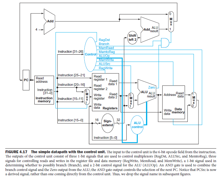
Add ALU Add result 4 Shift left 2 RegDst Branch instruction [31-26 Control ALUO ALUSrc RegWrite Instruction [25-2 Read register 1 Read register 2 register data Registers Read PC Instruction [20-16 Read ALU ALU Read MWrite data 2 AddressRead Address dataM [31-0] Instructioninstruction [15-11 5-11] ) Write Data 16 Sign- extend 32 Instruction [15-0] ALU control Instruction [5-0] FIGURE 4.17 The simple datapath with the control unit. The input to the control unit is the 6-bit opcode field from the instruction. The outputs of the control unit consist of three 1-bit signals that are used to control multiplexors (RegDst, ALUSrc, and MemtoReg), three signals for controlling reads and writes in the register file and data memory (RegWrite, MemRead, and MemWrite), a 1-bit signal used in determining whether to possibly branch (Branch), and a 2-bit control signal for the ALU (ALUOp). An AND gate is used to combine the branch control signal and the Zero output from the ALU; the AND gate output controls the selection of the next PC. Notice that PCSrc is now a derived signal, rather than one coming directly from the control unit. Thus, we drop the signal name in subsequent figures
Step by Step Solution
There are 3 Steps involved in it

Get step-by-step solutions from verified subject matter experts