

Question: fa0/1 90/1 90/2 90/1 fa0/2 K 90/2 fa0/1 fa0/2 K PC-PT PCO 2960-24TT Switcho ISR4331 Routero ISR4331 Routeri 2960-24TT Switch1 PC-PT PCI and the following
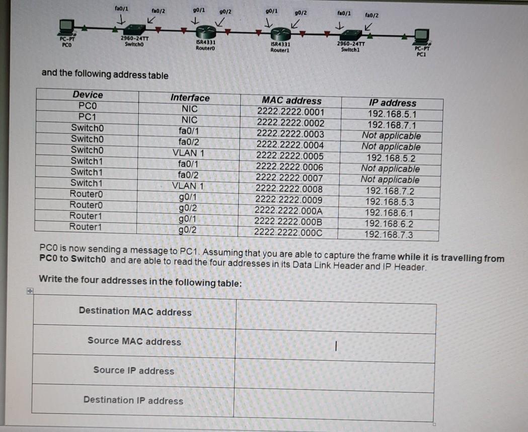
fa0/1 90/1 90/2 90/1 fa0/2 K 90/2 fa0/1 fa0/2 K PC-PT PCO 2960-24TT Switcho ISR4331 Routero ISR4331 Routeri 2960-24TT Switch1 PC-PT PCI and the following address table Device PCO PC1 Switch Switcho Switcho Switch1 Switch1 Switch1 Routero Routero Router1 Router1 Interface NIC NIC fa0/1 fa0/2 VLAN 1 fa0/1 fa0/2 VLAN 1 90/1 g0/2 g0/1 g0/2 MAC address 2222.2222.0001 2222.2222.0002 2222.2222.0003 2222.2222.0004 2222.2222.0005 2222.2222.0006 2222.2222.0007 2222.2222.0008 2222.2222.0009 2222.2222.000A 2222.2222.000B 2222.2222.000C IP address 192.168.5.1 192.168.7.1 Not applicable Not applicable 192.168.5.2 Not applicable Not applicable 192.168.7.2 192.168.5.3 192.168.6.1 192.168.6.2 192.168.7.3 PCO is now sending a message to PC1. Assuming that you are able to capture the frame while it is travelling from PCO to Switch0 and are able to read the four addresses in its Data Link Header and IP Header Write the four addresses in the following table: Destination MAC address Source MAC address Source IP address Destination IP address
Step by Step Solution
There are 3 Steps involved in it

Get step-by-step solutions from verified subject matter experts