

Question: need help on 2-5 2. Design a PLC program and prepare a typical 1/0 connection diagram and ladder logic program (Fig. 7-30) that will execute
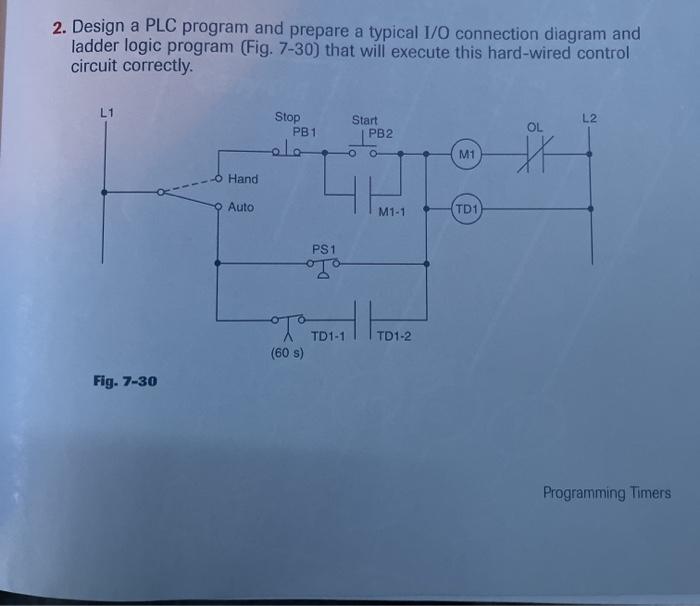
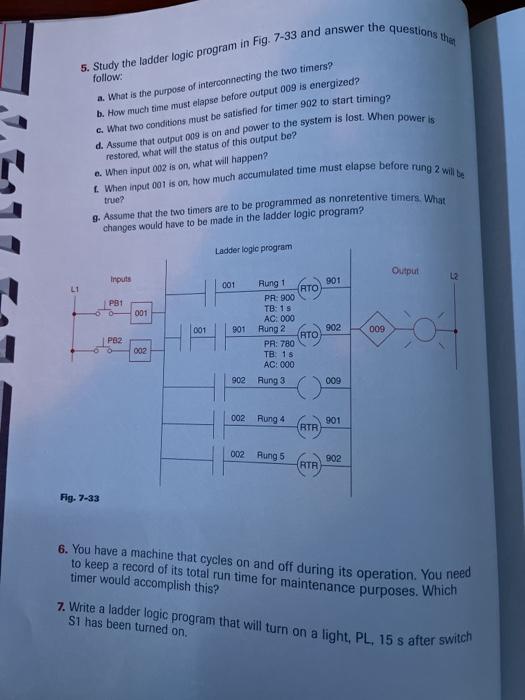
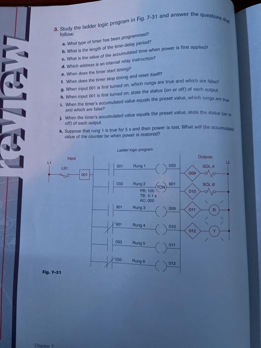
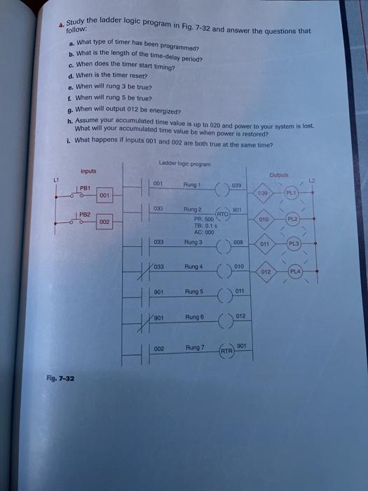
2. Design a PLC program and prepare a typical 1/0 connection diagram and ladder logic program (Fig. 7-30) that will execute this hard-wired control circuit correctly. L1 Stop PB1 L2 Start PB2 OL M1 O Hand Auto TD1 PS1 TO TO TDI1 Dual TD1-1 TD1-2 (60 s) Fig. 7-30 Programming Timers 5. Study the ladder logic program in Fig. 7-33 and answer the questions thao follow: a. What is the purpose of interconnecting the two timers? b. How much time must elapse before output 009 is energized? c. What two conditions must be satisfied for timer 902 to start timing? d. Assume that output 009 is on and power to the system is lost. When power is restored, what will the status of this output be? e. When input 002 is on what will happen? When input 001 is on, how much accumulated time must elapse before rung 2 wbt true? 9. Assume that the two timers are to be programmed as nonretentive timers. What changes would have to be made in the ladder logic program? Ladder logic program Output Inputs 2 001 901 L1 P31 001 001 901 902 009 Rng ! RTO PR: 900 TB: 15 AC: 000 Rung 2 RTO PR: 780 TB. 18 AC: 000 Rurg 3 PBZ 002 902 009 002 Rur 4 901 RTR 02 Rung5 902 RTR Fig. 7-33 6. You have a machine that cycles on and off during its operation. You need to keep a record of its total run time for maintenance purposes. Which timer would accomplish this? 7. Write a ladder logic program that will turn on a light, PL, 15 s after switch Si has been turned on. 3. Study the ladder logic program in Fig. 7-31 and answer the questions ROZ follow: a. What type of timer has been programmed? b. What is the length of the time-delay period? What is the value of the accumulated time when power is first applied d. Which address is an internal relay instruction? e. When does the timer start timing? When does the timer stop timing and reset itself? 9. When input 001 is first turned on, which rungs are true and which are false h. When input 001 is first turned on, state the status (on or off of each output When the timer's accumulated value equals the preset value, which rungu are true and which are false? When the timer's accumulated value equals the preset value, state the status (un er k. Suppose that rung 1 is true for 5s and then power is lost. What will the accumulated value of the counter be when power is restored? of of each output Ladder logic program Input Outputs LI L2 001 LS1 033 Aung SOLA 001 000 033 901 SOLB 010 Rung? TON PR: 100 TB: 0.1 AC: 000 Aung 3 901 009 011 901 Rung 4 010 012 033 Rung 011 033 Aung 6 012 o Fig. 7-31 Chapter 2
Step by Step Solution
There are 3 Steps involved in it

Get step-by-step solutions from verified subject matter experts